Here is an update regarding the design of the base for the cat toy that I have been building for my Introduction to Physical Computing final project. This post is a long time coming - I planned to post this information several weeks ago but was forced to wait due to the general workload surrounding finals.
Unfortunately, I was not able to finalize this project by the end of the semester due to issues that I encountered with the stepper motors, and creating a system of gears and pulleys that are able to move the cat toy structure (I've already created a post with information regarding the stepper motor-related issues, I will review the issues encountered when creating the gear and pulley systems here). That said, first let's take a look at the design for the cat toy base.
The Design of the Cat Toy Base
When I started working on the design for this device I envisioned using an existing cat scratching post as the base for my creation. This was an ideal solution since these toys feature a strong base that can withstand the tug from cats. Unfortunately, I did not find any existing products in a form factor that can work with my vision of this toy.
Once I realized that I had to create my own base structure, I decided that I wanted to build it using recycled materials. Considering how much Sasha likes cardboard scratching posts and the amount of cardboard boxes that are discarded in NY, I decided to use cardboard as the primary material for the base. The main considerations that drove my design included: allowing sufficient space to house the arm, laser, speaker, and proximity sensor; creating a shape that would appeal to the cat and allow for easy scratching; and making sure that the base was stable enough to withstand a beating from Sasha.
Here are a few important notes about the sketch designs featured below: first off, the light brown areas illustrate the internal compartment of the toy base where the chips, sensors, and motors will be stored; secondly, the two protruding structures at the top of the base will hold the toy wand and the laser; lastly, for the initial version of the toy I have decided to remove the cat laser (this will of course be reflected in all future pictures related to this prototype).
The Structure that Supports Movement
The biggest challenge I have encountered in developing this prototype is designing and building the mechanism of motion for the wand. Once I was able to get the motors working properly (which was a challenge in and of itself), I started working on finding a solution for the structure that would hold the wand, and for transferring the motion from the motors to move the wand.
After a considerable amount of research I decided to purchase an erector to create the structure for the wand. The specific set that I purchased is pictured here. This is a great solution because the parts in this set can be easily combined and recombined to created a strong structure that supports different types of movement.
Finding a solution for the gear and pulley mechanism was much tougher. The first challenge was to understand how gears and pulleys work together, so that I could design a system and find the appropriate parts. After doing some initial research, I decided to use Lego Mindstorm gears to build my initial prototype. Unfortunately, this approach did not work because the gear connection to the shafts was too loose, especially after the motor heated up.
After talking to some colleagues at ITP (thank you Michael K), I realized that what I needed was gears with hubs and set screws similar to the one featured on this page. These types of gears can be fastened securely to shafts of slightly varying thickness. SDP-SI has by far the largest selection of gears and pulleys on the web. Unfortunately, these components are not cheap.
The solution that I ultimately selected was to purchase a set of gears from Eitech that is compatible with the shafts from my erector set. The Girders and Gears website was a great resource that helped me find this solution. This site features useful information about various types of building sets and related gears and pulleys. Unfortunately, I have not yet had a chance to test these new gears. I plan on doing so as soon as I return to New York in mid-January.
One additional approach that I considered was creating my own gears, using a 3D sketching program and a laser cuter. Here is a link to step-by-step instructions for designing and producing custom gear sets.
Showing posts with label ITP-IntroPhysicalComp. Show all posts
Showing posts with label ITP-IntroPhysicalComp. Show all posts
Friday, January 1, 2010
Thursday, December 10, 2009
Creating Movement for the Cat Toy
Over the past couple of days I have struggled in my attempts to set up a stepper motor. Late last week my struggle continued as I tried to set-up three new stepper motors that I received for the cat that I am building. Having come home defeated I decided that the best course of action was for me to do some research regarding how stepper motors work so that I can improve my understanding and conceptual model of this component.
In the last hour I have discovered two really good overviews of how steppers work. The first is Mike Cook’s overview on his instructional blog; this is the second time that I link to Mike’s blog, he has a lot of great content for beginner's like me. This tutorial helped me finally understand how the coils are arranged and organized within the motor and how the stepping sequence is able to move the motor rotor through different positions. In retrospect it all seems obvious.
Another website that has content that is worth checking out is stepperworld.com. The tutorial here does not provide as thorough an overview of the inner workings of stepper motors. However, it does a better job at providing guidance for figuring out the proper wiring sequence of a stepper motor.
So what the hell did I learn about the topics mentioned above? Here is a brief overview but for more in-depth information check out the two links above.
Structure of the coils inside the motor
 The coils in stepper motors are wrapped around a structure that surrounds the rotor. The number of times that the coils are wrapped around the rotor determines the number of steps required for the motor to make one full rotation. For example if the coils are wrapped around 48 times, then the motor would take 48 steps to complete one full rotation. Here is an image from Mike Cook’s site that illustrates this design.

To move the motor the coils are energized in sequence. Motors can be used in two different modes: full-step and half-step. When two coils are energized at any given time the motor moves in full step, which provides greater torque but less precision. When the motor is energized one coil at a time it provides greater precision of movement (twice the number of steps per rotation) but less torque. Here is another image from Mike's blog that demonstrates how full-step movement works.
Now that I understood how stepper motors work, I had to figure out the proper step and wiring sequence to get the motor to work properly. I started by re-checking all wire connections to ensure that I attached the leads from the motors to the appropriate control pins (via the transistors) and power source pins. This was a good thing because I realized that I had attached one of the power wires to a control pin.
Once I the wiring was set-up properly I was still experiencing issues with the stepper motors. They would turn on and spin for 10 to 20 seconds, then they would stop working. I met with Xiaoyang, one of ITP's residents, regarding this issue. He recommended that I test the power source voltage and amperage. The motor’s rating is 5 volts at 1 amp. Based on Xioayang’s advice and my research online, I decided that I needed to find a power source that delivered twice the current required by the motor.
I purchased a 2 amp transformer from Radio Shack that can be set to output between 3v to 7v. It is a great little tool, and it brought my motors to life! I was dancing around the table when this happened. It seems like I may actually be able to bring my cat toy to life. My next challenge was getting multiple motors to run smoothly together smoothly. The code samples that I've found and the stepper motor library are not appropriate for controlling multiple motors - more on this on my next post on this subject.
In the last hour I have discovered two really good overviews of how steppers work. The first is Mike Cook’s overview on his instructional blog; this is the second time that I link to Mike’s blog, he has a lot of great content for beginner's like me. This tutorial helped me finally understand how the coils are arranged and organized within the motor and how the stepping sequence is able to move the motor rotor through different positions. In retrospect it all seems obvious.
Another website that has content that is worth checking out is stepperworld.com. The tutorial here does not provide as thorough an overview of the inner workings of stepper motors. However, it does a better job at providing guidance for figuring out the proper wiring sequence of a stepper motor.
So what the hell did I learn about the topics mentioned above? Here is a brief overview but for more in-depth information check out the two links above.
Structure of the coils inside the motor
The coils in stepper motors are wrapped around a structure that surrounds the rotor. The number of times that the coils are wrapped around the rotor determines the number of steps required for the motor to make one full rotation. For example if the coils are wrapped around 48 times, then the motor would take 48 steps to complete one full rotation. Here is an image from Mike Cook’s site that illustrates this design.Now that I understood how stepper motors work, I had to figure out the proper step and wiring sequence to get the motor to work properly. I started by re-checking all wire connections to ensure that I attached the leads from the motors to the appropriate control pins (via the transistors) and power source pins. This was a good thing because I realized that I had attached one of the power wires to a control pin.
Once I the wiring was set-up properly I was still experiencing issues with the stepper motors. They would turn on and spin for 10 to 20 seconds, then they would stop working. I met with Xiaoyang, one of ITP's residents, regarding this issue. He recommended that I test the power source voltage and amperage. The motor’s rating is 5 volts at 1 amp. Based on Xioayang’s advice and my research online, I decided that I needed to find a power source that delivered twice the current required by the motor.
I purchased a 2 amp transformer from Radio Shack that can be set to output between 3v to 7v. It is a great little tool, and it brought my motors to life! I was dancing around the table when this happened. It seems like I may actually be able to bring my cat toy to life. My next challenge was getting multiple motors to run smoothly together smoothly. The code samples that I've found and the stepper motor library are not appropriate for controlling multiple motors - more on this on my next post on this subject.
[note: most of this post was written during last weekend on December 4th]
Wednesday, November 25, 2009
Design for Cat Toy Controller - IPC Final Project
This evening I worked on the design of the joystick controller for my cat toy project. I decided to put the laser joystick on the lower left-hand corner, underneath two status lights (the first is power status, the second is laser status), in the center I have placed the joystick for the arm, and the bird call buttons are on the right-hand side. I am still considering switching the location of the bird call buttons and the large joystick. C
Here are my design documents. I plan to start building the controller tomorrow.
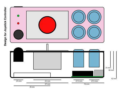
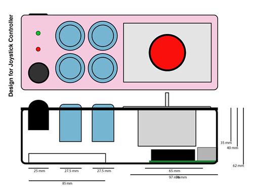
There are still a few things that I need to sort out. First, I need to figure out a solution to hold the thumb joystick in place. Second, I need to find wire that is softer and more pliable than the 22-gauge wire that I am accustomed to using. Last, I need to determine whether the final design will include a solderless or soldered breadboard.
Here are my design documents. I plan to start building the controller tomorrow.
There are still a few things that I need to sort out. First, I need to figure out a solution to hold the thumb joystick in place. Second, I need to find wire that is softer and more pliable than the 22-gauge wire that I am accustomed to using. Last, I need to determine whether the final design will include a solderless or soldered breadboard.
Tuesday, November 24, 2009
Testing the Cat Toy Controller Components - IPC Final Project
Earlier today I received my first shipment from Sparkfun. It contained the joysticks and buttons that I included in my previous post. The motors that I ordered won’t arrive until next week. So I decided to start by testing out the components for my cat toy controller, all of which have arrived.
I started by soldering wires to all the buttons and joysticks. I used my trusty new soldering machine along with an impromptu helping hands device, fashioned out of pieces of a styrofoam-like material. Since I enjoy learning how to solder this was a great opportunity to practice.
After soldering the components I assembled them on a breadboard. This exercise made it clear to me that I will likely need to use both of my Arduinos in this project – one for the toy itself, the other for the controller. I hadn’t given it much thought but originally I had planned to use only one Arduino (I can always consider using a multiplexer). That said, I like how by using two Arduinos it will be easier to add wireless functionality to this toy in the future.
While hooking up the components I discovered that the arcade-like joystick uses switches rather than potentiometers. Therefore, it has a limited resolution that is digital-like, which can only differentiate between nine different orientations; unlike the potentiometer-based joysticks that can differentiate between thousands of precise positions. It was designed for games like pacman, with more limited input requirements. It should work fine for my project (if it doesn’t I have a second thumb joystick as a back-up).
In regards to the other joystick, I noticed after setting it up that Sparkfun sells an inexpensive breakout board. I am considering purchasing this component because it will make it easier for me to mount the joystick in the controller. It also reduces the number of pins to 5 (from 10), which will help me minimize the wiring complexity.
After setting up the circuit I developed a short Arduino sketch that tests each component. This simple application reads input from each button and joysticks and writes their current state to the serial port. I created this sketch mindfully so that it can serve as the foundation for the final code.
Here is a brief overview of the next steps I need to take:
Design the box for the controller
Check connection with infrared sensor
Find cat scratching post that can serve as basis for the toy
Look at gears to move laser and arm
Thursday, November 19, 2009
Building My First Arduino Shield
Yesterday I built my first Arduino shield. I've been wanting to put one of these together for a long time as I am tired of having the disconnect and re-connect wires individually whenever I want to swap my Arduino between projects.
It took me about an hour and half to solder all of the tiny little pieces together. As you can see from the pictures, I did a pretty good job of putting this little sucker together. Well, at least it looks good as I have not tested the shield yet to confirm it is actually working.
This was by far the best soldering practice I've had to date. Very timely considering that I will be working on the Monome build this weekend. Planning on purchasing another one of these soon.
Tuesday, November 17, 2009
Interactive Cat Toy - Defining Requirements - IPC Final Project
On last Thursday I had a brief meeting with Tom to talk about my final project. Per my previous posts on this subject, I have decided to create an interactive cat toy. Over the past several days I have been working on the design of this device so that I can identify what parts I need to order. Here is a brief update regarding my toy concept, the new solutions and problems have arisen, and what components I am considering for this project.
Updates to the Concept
For the most part my cat toy concept has remained unchanged. The focus of the design is still the situated interaction between a cat and human and the main components have remained unchanged - the human participant will use an arcade-like joystick to control the laser, the sound and the arm. The cat will interact with these three elements of the toy.
Here is a quick overview of the changes that are under consideration: first, I would like to add an auto mode to this device to enable a cat to interact with the toy without human participation. The toy’s arm would self-activate and move randomly anytime it senses motion within a 40-cm distance. Second, I would like to create a game for the human participant when s/he is engaged with the toy. This will be a much bigger challenge that will likely not be addressed in my initial prototype.
New Solutions and Problems
Switching between modes: I have made a conscious attempt to limit the number of virtual modes provided by this device. For example, I have attempted to design this toy so that each joystick controls only one element of the toy. That said, the following modes will still exist in my design:
Earlier today I carried out a small experiment to observe Sasha’s response to the servo motor’s sound. Check out the short video below for a quick overview of my observations.
Proximity sensing: In order to add the automatic mode that I envision for this device I need to find a proximity sensing solution. My main requirement is that this solution needs to enable the toy to identify when a cat passes a certain threshold so that the appropriate functionality can be activated. Per this description I only need a digital, rather than analog, solution.
Finding the Right Parts
Considering my goal is to have an initial working prototype by early next week, I have started to identify the specific components that I want to use on this project. Some of these items I have already ordered, while others will be ordered later this week once I decide what is the best option. Here is an overview of the selection process.
Movement and Motors
To move the arm and laser pointer I originally considered using servo motors. However, due to concerns regarding the sound generated by these types of components I am now leaning towards using stepper motors instead. I carried out a good bit of research to find a servo motor that is silent, unfortunately, this does not seem to be a coveted feature for these types of motors. Here are some of the best sources for servos that I found online – robotshop and servocity.
Another consideration regarding the movement of the arm and laser beam, is the need for a mechanism that supports both panning and tilting. I was able to find a few pan and tilt mechanisms for sale on the servocity website. These options seem robust and only a bit expensive. That said, since I have decided to use a stepper motor I will need to find other options or create my own.
Control and Switches
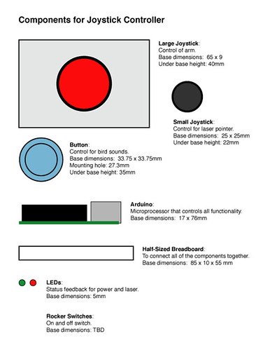
For the controller I have purchased the most important components – the joysticks and buttons. Where possible, I chose components that have an arcade-like or video game feel. Here is an overview of my selections:

This component has a great arcade like feel. It will be the main joystick on the controller and it will govern the movement of the arm with feathers. Cost and size considerations have led to my decision not to use this joystick for controlling the laser.

This small PS2-like joystick will be used to control the laser pointer. This joystick also incorporates a push button that will be used to turn on and off the laser device. The small size of this joystick denotes the secondary priority of this interaction element in comparison to the arm.

This light blue arcade-style button will be used to trigger the bird sounds. I have purchased 4 buttons in total, so that four separate sounds can be included in this prototype.
In regards to generating and controlling the sounds, I had originally planned to use one of the following two components: the WaveShield from Adafruit or the MP3 Trigger from Sparkfun. That said, based on advice from Tom (and my desire to minimize additional costs associated to building this prototype), I have decided to use my computer to generate the sound in the initial prototype. If all goes well with the user testing (or should I say cat testing) then I will likely add one of these components to the toy so that a computer does not need to be used.

To sense the cat’s presence/proximity I have decided to use a Sharp infrared range finder. This little component can sense ranges between 3 and 40 cm. It is ideal for my requirements because I plan to use this sensor for threshold detection within a small range only. It is much cheaper than the ultrasonic range finder options.
To turn the device on and off I plan to use a rocker switch similar to one pictured below from Sparkfun. To toggle between interactive and auto modes I will use a slide switch similar to the one from RadioShack that is featured in the picture below.
Additional Considerations
One additional consideration that I have not addressed is how to keep this cat toy “fresh”. Cats are extremely finicky animals and often grow tired of their toys after about 3 to 4 weeks. As I move forward with the design and development of my initial prototypes I will be looking for ideas on how to address this concern.
New Possibilities
In typical fashion, before I have even really gotten started with my current cat toy project I am already considering many improvements, updates, and related products. Here is a brief overview of two ideas I will consider incorporating into this or future projects (though not by finals time).
(1) I would like to use the toy as a medium for a game between the human and the cat. Initial ideas range from simple to complex. On the simple end we could add a counter to the proximity sensor and time the length of the cats presence in that proximity. We could also add a sensor to the arm so that it could sense when a cat is able to grab one of its feather. On the complex end we could use a video camera and together with a projector and the laser pointer, and have the human moving the laser beam around in an attempt to guide the cat to catch falling birds (which would be projected on the wall). The computer vision would be used to read images from the video camera to determine when the cat was able to catch the falling birds.
(2) Rather than have a cat toy that attempts to woe the cat, create a cat toy that can move around the room and is controlled via remote. I would still envision this cat toy having a remote controlled arm, though this arm would likely be designed differently (for example, it would have a 360-degrees motion since it would not be positioned against a wall).
Updates to the Concept
For the most part my cat toy concept has remained unchanged. The focus of the design is still the situated interaction between a cat and human and the main components have remained unchanged - the human participant will use an arcade-like joystick to control the laser, the sound and the arm. The cat will interact with these three elements of the toy.
Here is a quick overview of the changes that are under consideration: first, I would like to add an auto mode to this device to enable a cat to interact with the toy without human participation. The toy’s arm would self-activate and move randomly anytime it senses motion within a 40-cm distance. Second, I would like to create a game for the human participant when s/he is engaged with the toy. This will be a much bigger challenge that will likely not be addressed in my initial prototype.
New Solutions and Problems
Switching between modes: I have made a conscious attempt to limit the number of virtual modes provided by this device. For example, I have attempted to design this toy so that each joystick controls only one element of the toy. That said, the following modes will still exist in my design:
- On and off modes – as with most electronic gadgets, this cat toy will feature on and off modes that will be controlled by a rocker switch on the base of the toy.
- Interactive and automatic modes – as discussed in the “updates to the concept” section above, this toy will feature a secondary operation mode where it will sense and react to a cat’s presence/proximity. Control will be governed by a switch on the joystick controller.
- Game and freestyling modes – if a game-like element is added to the human participant’s interaction in the future, then we will want to provide the option for cat owners to select between a game and freestyle mode.
Earlier today I carried out a small experiment to observe Sasha’s response to the servo motor’s sound. Check out the short video below for a quick overview of my observations.
Proximity sensing: In order to add the automatic mode that I envision for this device I need to find a proximity sensing solution. My main requirement is that this solution needs to enable the toy to identify when a cat passes a certain threshold so that the appropriate functionality can be activated. Per this description I only need a digital, rather than analog, solution.
Finding the Right Parts
Considering my goal is to have an initial working prototype by early next week, I have started to identify the specific components that I want to use on this project. Some of these items I have already ordered, while others will be ordered later this week once I decide what is the best option. Here is an overview of the selection process.
Movement and Motors
To move the arm and laser pointer I originally considered using servo motors. However, due to concerns regarding the sound generated by these types of components I am now leaning towards using stepper motors instead. I carried out a good bit of research to find a servo motor that is silent, unfortunately, this does not seem to be a coveted feature for these types of motors. Here are some of the best sources for servos that I found online – robotshop and servocity.
Another consideration regarding the movement of the arm and laser beam, is the need for a mechanism that supports both panning and tilting. I was able to find a few pan and tilt mechanisms for sale on the servocity website. These options seem robust and only a bit expensive. That said, since I have decided to use a stepper motor I will need to find other options or create my own.
Control and Switches
For the controller I have purchased the most important components – the joysticks and buttons. Where possible, I chose components that have an arcade-like or video game feel. Here is an overview of my selections:
This component has a great arcade like feel. It will be the main joystick on the controller and it will govern the movement of the arm with feathers. Cost and size considerations have led to my decision not to use this joystick for controlling the laser.
In regards to generating and controlling the sounds, I had originally planned to use one of the following two components: the WaveShield from Adafruit or the MP3 Trigger from Sparkfun. That said, based on advice from Tom (and my desire to minimize additional costs associated to building this prototype), I have decided to use my computer to generate the sound in the initial prototype. If all goes well with the user testing (or should I say cat testing) then I will likely add one of these components to the toy so that a computer does not need to be used.
To turn the device on and off I plan to use a rocker switch similar to one pictured below from Sparkfun. To toggle between interactive and auto modes I will use a slide switch similar to the one from RadioShack that is featured in the picture below.
Additional Considerations
One additional consideration that I have not addressed is how to keep this cat toy “fresh”. Cats are extremely finicky animals and often grow tired of their toys after about 3 to 4 weeks. As I move forward with the design and development of my initial prototypes I will be looking for ideas on how to address this concern.
New Possibilities
In typical fashion, before I have even really gotten started with my current cat toy project I am already considering many improvements, updates, and related products. Here is a brief overview of two ideas I will consider incorporating into this or future projects (though not by finals time).
(1) I would like to use the toy as a medium for a game between the human and the cat. Initial ideas range from simple to complex. On the simple end we could add a counter to the proximity sensor and time the length of the cats presence in that proximity. We could also add a sensor to the arm so that it could sense when a cat is able to grab one of its feather. On the complex end we could use a video camera and together with a projector and the laser pointer, and have the human moving the laser beam around in an attempt to guide the cat to catch falling birds (which would be projected on the wall). The computer vision would be used to read images from the video camera to determine when the cat was able to catch the falling birds.
(2) Rather than have a cat toy that attempts to woe the cat, create a cat toy that can move around the room and is controlled via remote. I would still envision this cat toy having a remote controlled arm, though this arm would likely be designed differently (for example, it would have a 360-degrees motion since it would not be positioned against a wall).
Friday, November 13, 2009
IPC Class Notes, Communicating Wirelessly - November 11, 2009
In this week’s Introduction to Physical Computing class we had a brief discussion regarding microcontrollers, followed by and overview of how to use serial communications via wireless, then we briefly reviewed final project ideas.
Microcontrollers
When designing our final project Tom stressed the importance of taking into consideration the different form factors of Arduino and other microcontrollers available for our projects. These include:
The Arduino Family
There are several Arduino form factors available, and all are based on an AT Mega chip set. the Duenovemille is the standard unit that we have been using to date; the Nano is another standalone unit that features the same chip in a smaller form factor with a reduced number of pins; the Mini and Mini Pro are other small form factors that are designed to be mounted to a breadboard and features a chip with a bit less memory; the Mega is a larger unit that features considerably more memory and a large number of pins; lastly, the Lillypad is a chip designed for wearable computing projects.
Funnel IO and Gainer
Funnel IO (FIO) is an Arduiono clone that features an AT Mega and is integrated with an XBee on the back. Developed by Shigeru Kobayasho, FIO was created to work with Processing, ActionScripting, Max/MSP, Gainer and Wonderfl. Similar to the Arduino, FIO was created to enable artists and designers to integrate physical computing into their projects. Please note that the content on the Gainer website is mostly only available in Japanese – that said, it can be entertaining to use Google translation to read through it.
Illuminato X Machina
A new addition to the microcontroller offerings is the Illuminato X Machina. This chip attempts to add more capabilities and power to the world of microcontroller, without increasing the complexity of the development environment. This chip has an interesting design that is based on a cellular network. It allows users to increase the processing power by setting up networks of microcontrollers.
Serial Communications Using Wireless
Serial communication protocols are used by a large variety of components, including RFID, displays, motor and sensor controllers, to name a few. Wireless modules, such as the Xbee, connected to computers and Arduinos using serial.
To date, all of our explorations into serial protocols have focused on asynchronous types of communications. In order to use the XBee we need to use synchronous communications instead. Below is a brief refresher on these two concepts. It is important to note that many wired components also work with synchronous connections.
Asynchronous Communications
In asynchronous communications the connected devices each have their own clocks and send messages back and forward in an uncoordinated fashion, from a clock perspective. It is important to note that a programmer can use a coordination mechanism, such as call-and-response, to manage the communications.
Devices that are linked for asynchronous communications share three connections: two transmit and receive connections (each one set to an alternate direction), and a common ground.
Synchronous Communications
In synchronous communications the devices share a clock and send their messages in coordination with the clock pulses. Networks of devices that are connected synchronously, always feature a master and a set a slaves. The master is the device that sets the clock for all others.
Devices that are linked for synchronous communications share four connections: a Master In Slave Out (MISO) connection, a Master Out Slave In (MOSI) connection, a clock connection, and a common ground.
Components that can use synchronous serial communication have a pin called Chip Select. This pin enables the master device to connect to multiple devices using a single clock, MOSE and MISO pins, as long as it is directly connected to each slave chips Chip Select pins. In these types of circuits synchronous serial devices will only communicate on the MISO and MOSI pins if the status of the Chip Select pin is properly set.
Back to the Xbees
When setting up an Xbee on an Arduino you need to use the serial transmit (TX) and receive (RX) pins from each device. This will enable information to flow to and from both components. On the Arduino IO pins 0 and 1 are the RX and TX pins. It is important to disconnect the Xbee when uploading a program via serial to your Arduino. The reason being, if the Xbee is connected to the serial port then the Arduino can’t use this port to connect to the computer.
If multiple Xbees are connected to the same multimedia computer (or master) then each one of the chips will have its own address. Messages can be sent to a single address, or can be broadcast to all Xbee devices.
To set up an Xbee you first need to set it up using USB. For this you will need a USB to serial adapter for the Xbee, which converts data from traditional serial protocols (TTL and R-232) to the appropriate USB protocol. The most common adapter used for this task is the Xbee/USB breakout board (also called XB explorers).
Xbees use the AT Command Set, which was originally designed to drive modem communications. This protocol is widely known, and has been used for a long time. There are two different modes of communications used in the AT Command Set (and most similar protocols for that matter):
When using Xbees it is advisable to use a handshake (call-and-response) method so that we don’t encounter delays associated to buffer issues. When using multiple Xbees the handshake logic of the code is the same as the example we previously explored in class, for the most part. The difference is that we need to add logic on the receiving end to confirm where the data was sent from, and to determine where to send the next request.
Bluetooth
Bluetooth is another wireless protocol that is often used for wireless communication. However, Bluetooth only supports one to one communications, so all Bluetooth devices can be connected to a multimedia computer only and not to one another. Bluetooth also sets up sessions when they connect with a device, which requires a few seconds for initiation and closing a connection.
Microcontrollers
When designing our final project Tom stressed the importance of taking into consideration the different form factors of Arduino and other microcontrollers available for our projects. These include:
The Arduino Family
There are several Arduino form factors available, and all are based on an AT Mega chip set. the Duenovemille is the standard unit that we have been using to date; the Nano is another standalone unit that features the same chip in a smaller form factor with a reduced number of pins; the Mini and Mini Pro are other small form factors that are designed to be mounted to a breadboard and features a chip with a bit less memory; the Mega is a larger unit that features considerably more memory and a large number of pins; lastly, the Lillypad is a chip designed for wearable computing projects.
Funnel IO and Gainer
Funnel IO (FIO) is an Arduiono clone that features an AT Mega and is integrated with an XBee on the back. Developed by Shigeru Kobayasho, FIO was created to work with Processing, ActionScripting, Max/MSP, Gainer and Wonderfl. Similar to the Arduino, FIO was created to enable artists and designers to integrate physical computing into their projects. Please note that the content on the Gainer website is mostly only available in Japanese – that said, it can be entertaining to use Google translation to read through it.
Illuminato X Machina
A new addition to the microcontroller offerings is the Illuminato X Machina. This chip attempts to add more capabilities and power to the world of microcontroller, without increasing the complexity of the development environment. This chip has an interesting design that is based on a cellular network. It allows users to increase the processing power by setting up networks of microcontrollers.
Serial Communications Using Wireless
Serial communication protocols are used by a large variety of components, including RFID, displays, motor and sensor controllers, to name a few. Wireless modules, such as the Xbee, connected to computers and Arduinos using serial.
To date, all of our explorations into serial protocols have focused on asynchronous types of communications. In order to use the XBee we need to use synchronous communications instead. Below is a brief refresher on these two concepts. It is important to note that many wired components also work with synchronous connections.
Asynchronous Communications
In asynchronous communications the connected devices each have their own clocks and send messages back and forward in an uncoordinated fashion, from a clock perspective. It is important to note that a programmer can use a coordination mechanism, such as call-and-response, to manage the communications.
Devices that are linked for asynchronous communications share three connections: two transmit and receive connections (each one set to an alternate direction), and a common ground.
Synchronous Communications
In synchronous communications the devices share a clock and send their messages in coordination with the clock pulses. Networks of devices that are connected synchronously, always feature a master and a set a slaves. The master is the device that sets the clock for all others.
Devices that are linked for synchronous communications share four connections: a Master In Slave Out (MISO) connection, a Master Out Slave In (MOSI) connection, a clock connection, and a common ground.
Components that can use synchronous serial communication have a pin called Chip Select. This pin enables the master device to connect to multiple devices using a single clock, MOSE and MISO pins, as long as it is directly connected to each slave chips Chip Select pins. In these types of circuits synchronous serial devices will only communicate on the MISO and MOSI pins if the status of the Chip Select pin is properly set.
Back to the Xbees
When setting up an Xbee on an Arduino you need to use the serial transmit (TX) and receive (RX) pins from each device. This will enable information to flow to and from both components. On the Arduino IO pins 0 and 1 are the RX and TX pins. It is important to disconnect the Xbee when uploading a program via serial to your Arduino. The reason being, if the Xbee is connected to the serial port then the Arduino can’t use this port to connect to the computer.
If multiple Xbees are connected to the same multimedia computer (or master) then each one of the chips will have its own address. Messages can be sent to a single address, or can be broadcast to all Xbee devices.
To set up an Xbee you first need to set it up using USB. For this you will need a USB to serial adapter for the Xbee, which converts data from traditional serial protocols (TTL and R-232) to the appropriate USB protocol. The most common adapter used for this task is the Xbee/USB breakout board (also called XB explorers).
Xbees use the AT Command Set, which was originally designed to drive modem communications. This protocol is widely known, and has been used for a long time. There are two different modes of communications used in the AT Command Set (and most similar protocols for that matter):
- Command Mode: communications to the modem.
- Data Mode: communications through the modem.
- Series 1 uses 802.14.5 command set. This protocol is more limited than the series 2 but it is also much simpler. It provides more than enough functionality for most types of uses and is the right way to go for most applications.
- Series 2 uses a command set that supports mesh networking. It is much more complex to use than series 1. Mesh networks are made up of devices configured as “controllers” (c), “routers” (r), and “end-points” (e). The “routers” essentially act as post office boxes that hold and distribute messages to the end point. Since the end points don’t always have to stay on this is a more energy efficient system.
- Address of Xbee chips (destination)
- Address of multimedia computer (source)
- Pan ID that enables to join Xbees into groups, so that different groups of Xbees don’t conflict with one another. Check out the pan ID list available on the Physical Computing website at ITP to select an unused port.
When using Xbees it is advisable to use a handshake (call-and-response) method so that we don’t encounter delays associated to buffer issues. When using multiple Xbees the handshake logic of the code is the same as the example we previously explored in class, for the most part. The difference is that we need to add logic on the receiving end to confirm where the data was sent from, and to determine where to send the next request.
Bluetooth
Bluetooth is another wireless protocol that is often used for wireless communication. However, Bluetooth only supports one to one communications, so all Bluetooth devices can be connected to a multimedia computer only and not to one another. Bluetooth also sets up sessions when they connect with a device, which requires a few seconds for initiation and closing a connection.
Playing with Motors IPC Lab (Continued)
Earlier this week I put together a short post regarding the motor lab for IPC. As I outlined in my post, I encountered a problem when working on the H-bridge lab. The Arduino was constantly switching off and on and when I moved the potentiometer to change the speed and direction of the motor. Therefore, yesterday I decided to re-do this part of the lab, adding a capacitor to the circuit to regulate the voltage during start up and moments where a lot of resistance is being placed on the motor.
I am happy to report that when I re-did the lab I was able to get everything working properly. As you can see in the video below I was able to get the potentiometer to control the motor smoothly while alternating speed and direction.
Considering that I will need to use motor to enable movement for two aspects of my final project, I enjoyed having the opportunity to practice building circuits that require diodes and capacitors (as I have little experience working with these components).
Wednesday, November 11, 2009
Interactive Cat Toy Initial Concept Ideas - IPC Final Project
As I outlined in my previous post, my final project for IPC will be an interactive cat toy. Before I share my initial concept I want to go over the considerations that guided my initial design choices. Over the next four weeks this design will evolve and change based on technical, esthetic, usability, and fun-factor considerations. Enough preamble, let's dive right in.
Inspiration for the Project
My main inspiration for this project comes from my cat, Sasha. That said, she can't take all the credit (or blame) because I've always liked cats even though I never owned one. Lauren's family's cat, Suzie, also deserves some of the responsibility. Since I've been hanging out with these two cats I've evolved from a cat-friendly to cat-obsessed. Here is a short video of Sasha, Suzie and a sickeningly cute kitten that we rescued three months ago, Little Scrappy.
Sasha is definitely the cat that will have the biggest influence on this project. My knowledge of her likes and dislikes guided my selection of the types of interaction that I want to integrate in this toy. For example the decision to include sound was driven by Sasha's reaction to bird sounds that my wife recently played at home.
Main Design Objectives and Considerations
My objective is to create a toy that deliver an experience that is fun for the cat and the human. All design decisions need to be made with this objective in mind. The main requirements that will also guide my decision are:
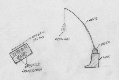
The concept for my interactive cat toy is a remote controlled device that contains: (a) a laser pointer, controllable by a joystick, to play with cats that are across the room; (b) several bird chirping sounds, controllable via buttons, to attract the cat over to the toy; (c) an arm with a hanging string and feathers, controllable by a joystick, to play with a cat that is near the toy.
I envision the toy having an L-shaped base which is meant to provide stability and can be secured to a wall. The arm protrudes from the top of the vertical leg of the L-shaped base. Next to the arm, a small ball-like object holds the laser pointer (I am considering using a mirror to move around the laser, as in the FroliCat Bolt toy). The motors and wiring are hidden in the base of the toy.
The remote control would have a old-school arcade video game feel, though I am considering to use PS joysticks. Though originally I planned to only use buttons for the bird sounds, I will likely needed to add a laser on/off button to the controller as well. I may choose to reduce the number of sounds down the three, so that I can keep the number of buttons on the remote to a minimum.
Here is my initial drawing of the cat entertainment center and remote:
Once the initial prototype is build I would like to extent this toy by creating a wireless remote and adding internet connectivity (both video feed and control). That said, the core of my concept is the situated interaction between the cat and human, so I will keep my focus here for the next four weeks. Then we can see whether it makes sense to extend this concept into these different areas of functionality.
Important Next Steps
Here is a brief overview of my next steps with this project:
Inspiration for the Project
My main inspiration for this project comes from my cat, Sasha. That said, she can't take all the credit (or blame) because I've always liked cats even though I never owned one. Lauren's family's cat, Suzie, also deserves some of the responsibility. Since I've been hanging out with these two cats I've evolved from a cat-friendly to cat-obsessed. Here is a short video of Sasha, Suzie and a sickeningly cute kitten that we rescued three months ago, Little Scrappy.
Sasha is definitely the cat that will have the biggest influence on this project. My knowledge of her likes and dislikes guided my selection of the types of interaction that I want to integrate in this toy. For example the decision to include sound was driven by Sasha's reaction to bird sounds that my wife recently played at home.
Main Design Objectives and Considerations
My objective is to create a toy that deliver an experience that is fun for the cat and the human. All design decisions need to be made with this objective in mind. The main requirements that will also guide my decision are:
- easy for the user and the cat to use - no instruction manual needed.
- offer fun ways for the cat to play from both far away and near by.
- able to attract the cat's attention if the owner wants to initiate a play session.
- esthetically pleasing enough to put in your NY studio or one-bedroom apt.
- provide auto mode that plays with the cat while the owner is away.
- make sure that toy is able to handle a lot of punishment because Sasha can dish it out.
- focus on the situated interaction between cat and human to maximize connection.
- consider using sound to attract cats (very effective for Sasha).
- leverage video game buttons and joysticks to give the remote control a fun feel.
- make sure all cables are cat safe, since they can be cable eaters.
- use an power plug rather than battery to better support prolonged use of auto mode (maybe wrong decision from sustainability perspective?)
- keep in mind possible future upgrades (web connection with video feed and online controls, wireless remote control, etc).
The concept for my interactive cat toy is a remote controlled device that contains: (a) a laser pointer, controllable by a joystick, to play with cats that are across the room; (b) several bird chirping sounds, controllable via buttons, to attract the cat over to the toy; (c) an arm with a hanging string and feathers, controllable by a joystick, to play with a cat that is near the toy.
I envision the toy having an L-shaped base which is meant to provide stability and can be secured to a wall. The arm protrudes from the top of the vertical leg of the L-shaped base. Next to the arm, a small ball-like object holds the laser pointer (I am considering using a mirror to move around the laser, as in the FroliCat Bolt toy). The motors and wiring are hidden in the base of the toy.
The remote control would have a old-school arcade video game feel, though I am considering to use PS joysticks. Though originally I planned to only use buttons for the bird sounds, I will likely needed to add a laser on/off button to the controller as well. I may choose to reduce the number of sounds down the three, so that I can keep the number of buttons on the remote to a minimum.
Here is my initial drawing of the cat entertainment center and remote:
Once the initial prototype is build I would like to extent this toy by creating a wireless remote and adding internet connectivity (both video feed and control). That said, the core of my concept is the situated interaction between the cat and human, so I will keep my focus here for the next four weeks. Then we can see whether it makes sense to extend this concept into these different areas of functionality.
Important Next Steps
Here is a brief overview of my next steps with this project:
- Update toy design based on feedback from class
- Determine dimensions of the toy
- Design movement mechanisms for arm and laser
- Identify the motor strength needed to move arm
- Identify materials for building base and controller
- Design circuit for controller and base
- Purchase component parts
Interactive Cat Toy Competitive Research - IPC Final Project
Over the weekend I decided that my final project for the Introduction to Physical Computing class would be a cat toy. I have wanted to design cat toys and furniture since before I came to ITP; I will even admit that I am a cat video offender. Nonetheless, this is the perfect opportunity for me to stop talking about wanting to create a cat toy and start actually doing it.
To start off the design process I did a bit of research regarding cat toys, focusing my attention on any interactive electronic offering I could find. I started off by looking at several previous projects from ITP, then I looked at commercial toys. Here is an overview of what I found:
Previous Cat Toys from ITP
The Hanimustv by Aram Chang
The Hanimustv is a cat toy that was developed as a thesis project for last year. It is a “peek” and “hide” game that is controlled by a small remote control with arcade-style buttons. Small wooden cylinders are raised out of a box in response to button presses on the remote. The cylinders return to their original position once the button is released.
From a technology perspective, this cool toy uses an Arduino connected to buttons that controls a set of solenoids, which move the cylinders. Check out this cool user test video - the users testing the toy were of course cats, rather than humans.
Toy characteristics:
- Interactivity between cat and human
- Movement of physical objects for cat
- Physical controls for human
The Meowzer by Gordie and Emily
Another ITP cat toy that I discovered is called Meowzer; it was developed last spring semester by Gordie and Emily. Meowzer has a rotating top part that holds five arms. Four of these arms have dangling strings that hold small fluffy cat toys (one of which has a laser light). The fifth arm holds a small bunch of feathers and is the only one that can move up and down. The toy is controlled by an application that runs on a laptop computer.
From a technology perspective, this toy uses an Arduino that is connected to the following main components: DC motor that rotates the top part; Servo motor that moves the fifth arm up and down; and a laser light attached to one of the cat toys, in the mouth position. The application that controls the toy was developed in Processing.
Here is a link to the documentation about this project from Gordie’s blog. The documentation is comprehensive and features a nice video of the finished product.
Toy characteristics:
- Interactivity between cat and human
- Movement of physical objects and light for cat
- Virtual controls for human
Unnamed Toy by Patrick Proctor
The last ITP-developed cat toy that I found was developed by Patrick Proctor for our Introduction to Physical Computing class. This toy was designed to enable two cats to interact. It essentially features two separate toys that are connected. The first toy is a tennis ball on a metal spring that is secured to a wooden base; the cat plays with it by batting the ball around. The second toy is a laser pointer that moves from side to side; the cat plays with it by following the laser light reflection on walls. The movement of the laser pointer is partially governed by interactions with the tennis ball.
Here is a link to a blog post from Patrick where you can find pictures and an overview of his project.
Toy characteristics:
- Interactivity between cat and cat
- Movement of physical objects and light
- Physical controls for cat (or human)
Consumer Cat Toy Examples
Here I will focus my exploration on electronic cat toys only. That is not to say that old-school cat toys (such as plush toys, scratching pads, crinkly balls, laser pointers, shoe laces, etc) will not serve as part of my inspiration for this project. Ultimately, I want to create an electronic cat toy that rivals the interactivity provided by a stick with a piece of shoelace tied at the end, which to this day remains Sasha’s favorite toy.
Run Rascal
This is the only cat toy from the bunch that I have personally owned. It is a remote controlled mouse. My cat, Sasha, liked this toy well enough. The only problem we encountered was that the mouse is not able to run on carpets, which is where sasha likes to hang out the most. It is definitely the most interactive electronic cat toy that I have seen on the market.
Toy characteristics:
- Interactivity between cat and human
- Movement of physical object for cat
- Physical controls for human
The electronic toys listed below offer minimal or no interactivity. That is not to say that they are not much enjoyed by cats.
FroliCat Bolt
This is a relatively new cat toy that is relatively simple. It amounts to a laser light mounted in a well thought out container that moves the laser around a room. The laser moves based on the movement of a reflective mirror, rather than the movement of the light source itself. This toy offers an interesting mechanism, though it is not truly interactive (unless you hold it in your hand and use it like a traditional laser pointer).
Toy Characteristics:
- Movement of light for cat
- Limited interactivity provided
Mouse in the House
This is a cat toy that looks like a small diorama of a living room and features a track on which small toy mouse runs. The timing of the appearance of the small mouse can be programmed to enable the toy to entertain unattended cats for long periods of time. For the most part the toy seems to appeal to cats, though pet owners complain about the loud noise of the motor. Though this toy does not provide direct interactivity, it does offer the toy owner the ability to program the frequency of the mouse movement.
Toy Characteristics:
- Movement of physical object for cat
- Limited interactivity provided
Tuesday, November 10, 2009
Switching High-Load Circuits Lab, Playing with Motors
Earlier this week I was finally able to get caught up on my lab work for Introduction to Physical Computing. The lab exercises for last week involved setting up two circuits using DC motors: (1) Transistor Lab - simple circuit that rotates the motor in one direction only; (2) H-Bridge Lab - more complex circuit that enables bi-directional rotation of the motor.
Below is a short video that features the final circuits that I set-up. This is followed by an overview of the issues that I encountered and the code for the Arduino that I developed.
Issues and Solutions
The first issue that I encountered on this lab was finding the right motor to test. Initially I wanted to test a motor with at least a 12v load. After spending some time at local Radio Shack stores, I decided against buying a new and larger motor (e.g. 12V). So I used the 3v-6v motor that came with my parts kit.
Once the motor had been selected I worked on setting up the uni-directional circuit. At first I attempted to run the circuit without soldering the wire to the motor; as expected this did not work. After soldering the wires to the motor the circuit was working fine.
Next up I moved to work on the bi-directional circuit. As outlined in my notes from class last week, in order for a motor to work in both directions we need to reverse the flow of electricity going through the motor. This is where the H-bridge comes in handy. It couples four darlington transistors in a small package specifically for this purpose. Setting up this circuit took no time.
That said, I did encounter an issue when I was playing around with the Arduino code after the circuit had been tested. The changes I made to the Arduino code included setting up a potentiometer to control the speed and direction of movement (code included below). When running this sketch my Arduino seems to disconnect and reconnect to the multimedia computer continuously.
My guess is that this may be caused by the Arduino is experiencing a brownout when the motor is pulls a lot of electricity from the circuit (e.g. on start-up and when faced with resistance). I plan to try adding some capacitors to the circuit to resolve this issue. If you have any suggestions please leave them in the comments section.
Arduino Code - Bi-Directional Motor
Here is the code that I created for the H-bridge lab. I used the sketch provided by Tom Igoe for this lab as the foundation for this code.
/*
 * LAB - BI-DIRECTIONAL MOTOR
 * code based on sketch from Tom Igoe
 * modified by Julio Terra
 */

  const int potPin = 1;       // Analog in 0 connected to the potentiometer
  const int motor1Pin = 3;    // H-bridge leg 1 (pin 2, 1A)
  const int motor2Pin = 4;    // H-bridge leg 2 (pin 7, 2A)
  const int enablePin = 9;    // H-bridge enable pin
  const int ledPin = 13;      // LED

 int potValue = 0;            // value returned from the potentiometer
 int motorSpeed = 0;          // speed of the motor

 void setup() {

   // open serial port for debugging
   Serial.begin(9600);

    // set all the other pins you're using as outputs:
    pinMode(motor1Pin, OUTPUT);
    pinMode(motor2Pin, OUTPUT);
    pinMode(enablePin, OUTPUT);
    pinMode(ledPin, OUTPUT);

    // set enablePin high so that motor can turn on:
    digitalWrite(enablePin, HIGH);

    // blink the LED 3 times. This should happen only once.
    // if you see the LED blink three times, it means that the module
    // reset itself,. probably because the motor caused a brownout
    // or a short.
    blink(ledPin, 3, 300);

 }

 void loop() {

   // read the potentiometer, convert it to 0 - 255:
   potValue = analogRead(potPin);

    // if the switch is high, motor will turn on one direction:
    if (potValue < 512) {
      digitalWrite(motor1Pin, LOW);   // set leg 1 of the H-bridge low
      digitalWrite(motor2Pin, HIGH);  // set leg 2 of the H-bridge high
      motorSpeed = map(potValue, 0, 511, 255, 100);  // set motor speed based on pot position
    }
    // if the switch is low, motor will turn in the other direction:
    else {
      digitalWrite(motor1Pin, HIGH);  // set leg 1 of the H-bridge high
      digitalWrite(motor2Pin, LOW);   // set leg 2 of the H-bridge low
      motorSpeed = map(potValue, 512, 1023, 100, 255);  // set motor speed based on pot position
    }

   // set new motor speed using analog write on the enablePin
   analogWrite(enablePin, motorSpeed);

   // de-bug by sending potValue through Serial
   Serial.print("potValue: ");
   Serial.print(potValue);
   Serial.println();
 }

  /*
    blinks an LED
   */
  void blink(int whatPin, int howManyTimes, int milliSecs) {
    int i = 0;
    for ( i = 0; i < howManyTimes; i++) {
      digitalWrite(whatPin, HIGH);
      delay(milliSecs/2);
      digitalWrite(whatPin, LOW);
      delay(milliSecs/2);
    }
  }
IPC Class Notes, Controlling Motors - Oct 27, 2009
During last week’s Intro to Physical Computing Class we focused on learning how to control motors and other heavy-loads using relays and transistors. These two components enable circuits with small current and voltage to control larger ones. Here is an overview of how they work, and how to set them up:
Relays
Relays use inductance to enable small DC circuits to control larger DC or AC ones. Inductance refers to the phenomenon where electricity, which is running through a circuit, creates a magnetic field around the circuit.
Relays use these types of magnetic fields to close a physical switch that completes a larger circuit. The magnetic field is generated every time that electricity flows through the small load bearing circuit on the relay. From a physical perspective, a relay is essentially a coil that is wrapped around a reed switch. When electricity runs through the coil circuit it generates a magnetic fields that closes the switch.
Relays have at least 4 pins, 2 pins for the small circuit that generates the magnetic field, 2 pins for the larger circuit that is switched by the relay.
Due to the physical/mechanical nature of relay switches this solution can only support digital communications between circuits. The speed of the connection is also slow because. The main benefit of the relay is that you can control an AC current from a DC source.
Transistors
Transistors also enable small circuits to switch circuits with higher loads. Unlike the relays, these are non-mechanical switches. This means that they have a faster speed of reaction and are able to communicate analog data.
Transistors are made of different types of silicon. The arrangement of these silicon layers enable one lead, with a small current or voltage, to control the flow of electricity through two other leads, with larger current or voltage. If no electricity is provided to the controlling lead then no electricity will flow through the bigger circuit.
The leads on a transistor are referred to as: the base, which is connected to the microcontroller and accepts a small load, such as pulses from an output pin; the collector, which is connected to a higher voltage source; the emitter, which is connected to ground.
Motors and Solenoids
Motors work by having two magnets surrounded by coils. The electricity that goes through the motor creates an electric field that causes the magnets to spin. When the motor is turned off the magnets will continue to spin temporarily, this creates a current in the reverse direction.
When working with motors it is important to consider issues associated to its physicality and mechanical nature. First and foremost, the response time provide by motors differs considerably from electronic components such as LEDs. For example, to get a motor going it requires that sufficient power accumulate to overcome the initial inertia of the motor.
Motors create a reverse flow of electricity when they are stopping due to the phenomenon of inductance that is used to move the motors. This has some important repercussions when building circuits that include motors.
First, you often need to use diodes. As an example, when hooking up motors and transistors it is important to include a diode in circuits where a transistor is used to control a motor or solenoid. This diode is used to ensure that reverse electricity will not flow through the transistor, as this would ruin it. For this to work, the diode needs to enable electricity to flow in the direction from the emitter to the collector
Second, you need to use capacitors. Adding a capacitor between the voltage source and the microcontroller helps ensure that the microcontroller gets sufficient power, even if the motor reduces the overall amount of energy available in the circuit (as it does when it is first turned on is facing resistance). I encountered this problem when working on the motor movement lab earlier this week.
Controlling Motors
The direction in which a motor spins is controlled by the direction of the flow of electricity. To control motor direction we need to create a circuit that includes four transistors as outlined in the circuit diagram below.
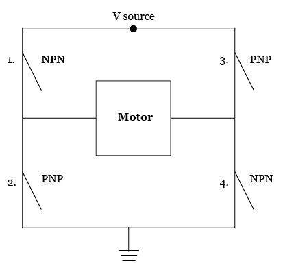
H-Bridges simplify the creation of circuits like the one above. They contain a network of transistors that enable the controlling of motor direction and speed. These components can support two separate motors, and have multiple input and output pins for each motor. Check out the diagram below from this week’s lab, it provides an overview of all pins on an H-Bridge.

Relays
Relays use inductance to enable small DC circuits to control larger DC or AC ones. Inductance refers to the phenomenon where electricity, which is running through a circuit, creates a magnetic field around the circuit.
Relays use these types of magnetic fields to close a physical switch that completes a larger circuit. The magnetic field is generated every time that electricity flows through the small load bearing circuit on the relay. From a physical perspective, a relay is essentially a coil that is wrapped around a reed switch. When electricity runs through the coil circuit it generates a magnetic fields that closes the switch.
Relays have at least 4 pins, 2 pins for the small circuit that generates the magnetic field, 2 pins for the larger circuit that is switched by the relay.
Due to the physical/mechanical nature of relay switches this solution can only support digital communications between circuits. The speed of the connection is also slow because. The main benefit of the relay is that you can control an AC current from a DC source.
Transistors
Transistors also enable small circuits to switch circuits with higher loads. Unlike the relays, these are non-mechanical switches. This means that they have a faster speed of reaction and are able to communicate analog data.
Transistors are made of different types of silicon. The arrangement of these silicon layers enable one lead, with a small current or voltage, to control the flow of electricity through two other leads, with larger current or voltage. If no electricity is provided to the controlling lead then no electricity will flow through the bigger circuit.
The leads on a transistor are referred to as: the base, which is connected to the microcontroller and accepts a small load, such as pulses from an output pin; the collector, which is connected to a higher voltage source; the emitter, which is connected to ground.
Motors and Solenoids
Motors work by having two magnets surrounded by coils. The electricity that goes through the motor creates an electric field that causes the magnets to spin. When the motor is turned off the magnets will continue to spin temporarily, this creates a current in the reverse direction.
When working with motors it is important to consider issues associated to its physicality and mechanical nature. First and foremost, the response time provide by motors differs considerably from electronic components such as LEDs. For example, to get a motor going it requires that sufficient power accumulate to overcome the initial inertia of the motor.
Motors create a reverse flow of electricity when they are stopping due to the phenomenon of inductance that is used to move the motors. This has some important repercussions when building circuits that include motors.
First, you often need to use diodes. As an example, when hooking up motors and transistors it is important to include a diode in circuits where a transistor is used to control a motor or solenoid. This diode is used to ensure that reverse electricity will not flow through the transistor, as this would ruin it. For this to work, the diode needs to enable electricity to flow in the direction from the emitter to the collector
Second, you need to use capacitors. Adding a capacitor between the voltage source and the microcontroller helps ensure that the microcontroller gets sufficient power, even if the motor reduces the overall amount of energy available in the circuit (as it does when it is first turned on is facing resistance). I encountered this problem when working on the motor movement lab earlier this week.
Controlling Motors
The direction in which a motor spins is controlled by the direction of the flow of electricity. To control motor direction we need to create a circuit that includes four transistors as outlined in the circuit diagram below.
H-Bridges simplify the creation of circuits like the one above. They contain a network of transistors that enable the controlling of motor direction and speed. These components can support two separate motors, and have multiple input and output pins for each motor. Check out the diagram below from this week’s lab, it provides an overview of all pins on an H-Bridge.
Friday, November 6, 2009
Media Controller Project - Phase 4
Yesterday we finalized and presented our media controller project for Introduction to Physical Computing class. Here I will share a video of the final working (or at least mostly working) prototype, then provide an overview of the building process for the physical interface, and go over some of the final updates made to the processing and arduino code. I will wrap up this post by sharing some ideas on how to evolve this device so that I could deliver on its full potential.
Overview of the Project
The objective of our project was to create a media control surface that controls modulation and filtering of sound, and is compatible with existing music production applications. The physical interface is comprised of a square surface and a puck- or mouse-like object. The surface is like a two dimensional matrix, each dimension, or axis, of this matrix controls a specific filter or effect. The location of the object relative to each axis of the surface determines the level of the effects and filters.
I will soon add a video to this post that demonstrates our prototype in action along with some pictures from the build process.
In its current state we are able to mimic the functionality that we envisioned, though the system is not able to fully deliver the functionality on its own. We have fully figured out the software end of the application, however, work still needs to be done on the physical computing interface. More on that when I dive into the details of the design and build process for this device.
Building the Matrix Light Grid
Zeven was taking the lead on building the physical computing interface. I helped out in the design of the circuits for the LED lights, and the Arduino-based controller puck/mouse. Here is an overview of this process, our solution, and the issues that we still need to be resolved.
Our first attempt at setting-up the LED circuit was done without much thought. This resulted in the burn out of an entire row of LEDs. After this initial failure we decided to take the time to design the circuit and review the design with a resident before building and testing it. Here are the two designs that we reviewed, the first one was our preferred and chosen design.
Design Option 1 - Preferred and Selected
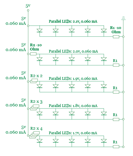
Design Option 2 - Considered
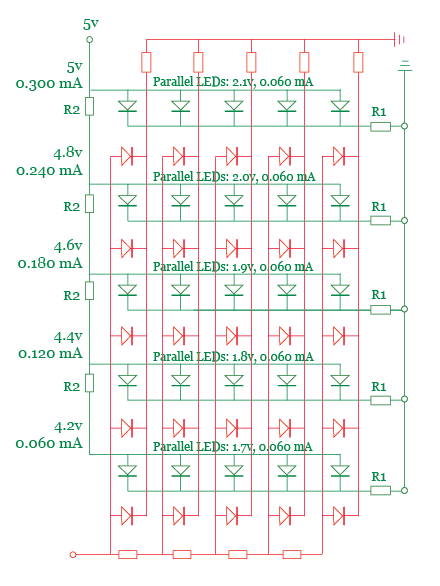
Once we agreed upon the design of the circuit we moved ahead with producing it. During the build process we used a multi-meter to check the amount of voltage being consumed by each row of LEDs. Based on my calculations I decided to use a resistor ladder with steps of 10 to 50 Ohms. The readings from the circuit confirmed our expectations, the increasing amount of resistance applied to each row in the circuit decreased the amount of voltage available to the LEDs on that row.
The next step in the build process involved setting up a test with a photocell to confirm that it was able to detect the variance in brightness of each row of LEDs. The initial tests were not successful, so we iterated through many rounds of other tests where we: added aluminum foil to increase the brightness of the lights, glued down the LEDs so that they are equal equidistant from the sensors, added a second photosensor to the controller object.
These changes helped us improve the quality of the sensor readings but they did not fully solve the problem. The final change that we made to the system was based on a suggestion from Tom. He recommended that, in order to improve the sensitivity of the system, we should use potentiometers to test different resistances for the sensor and LED circuits. We took this advice to heart and bought several 15-turn 1K mini-pots. These great little components helped us fine-tune the voltage of each LED row and the photosensors.
Unfortunately, this still did not fully solve our issues. The readings from the photosensors are not sufficiently consistent, even when smoothed via averaging. As an example, two LEDs that, connected in parallel on the same row and with the same amount of resistance, often gave different readings. This issue may be caused by the construction of each LED light box is not perfect, hence small amounts of light leakage may be responsible for the unexpected variances.
In the end our media controller works somewhat erratically due to the issues discussed above. Now I will dive into the software side of the mapping problem, determining how to map the readings from the controller to an appropriate MIDI message that can be delivered to Ableton.
Finalizing the Software
The core of the Arduino and Processing applications had been completed by the middle of last week. Therefore, our focus was on integrating the final physical interface with the multimedia computer and mapping readings from the serial port to appropriate MIDI messages.
Luckily, the integration process was quick and easy, unlike our attempts to map the readings from the photosensors. Due to the erratic values we received, we had to give up on our initial idea of using clear value ranges to determine which row and column of LEDs was being measured.
We were able to get the system to work partially by measuring the readings from each individual LED and then program a range based on that reading into the software. Unfortunately, due to light leakage and other potential contributors to our issue, we have not been able to achieve the resolution or smoothness that we hoped to.
Here is a link to the code from the final Processing and Arduino sketches.
Continuing to Improve the Interaction
Our original project idea was a more complex system that included several objects representing different instruments. Therefore, this is an obvious path that can be taken to increase the functionality of this prototype. However, before we consider extending the capabilities offered by this device we should examine how to solve the current implementation issues.
Two interesting ideas came up in class for solving the current issue with the system. Tom suggested that we add dark strips to the board. This would enable the photosensors to better detect movement of the controller. An accelorometer could be used to detect the direction of the movement, especially in a device where the controller’s orientation is pre-defined by a mechanism like the one that Zeven built.
The second suggestion came from Patrick. He asked whether we had considered using light filters coupled with multiple photosensors (e.g. having a photosensor for each color) to enable the system to better determine the location of the controller. I believe that these two approaches could be combined to improve the basic performance and increase the resolution offered by the system.
The final idea, which may hold the most potential, came to me as a result of examining another team’s media controller project. My inspiration came from a music sequencer that leverages switches designed as round holes, a conductive metal is visible on two opposite edges of each hole. In this design the switches are closed by the insertion of a metal ball in the round hole.
My vision is to build a surface comprised of similar round switches coupled with a controller that features small metal plates on the bottom. The controller would always close multiple switches at a time, thus providing an accurate mapping of its location to the system. The user would have the freedom to hold the controller in which ever direction they desire, assuming the proper designed can be created for the metal plates underneath the controller.
LED lights could be placed in the holes and used to display the current setting of the effects being controller. This would allow for the user to hot swap the effects being controlled by the unit, since the system would be able to communicate via the lights.
The one requirement (and reservation) I have about this design is how to make sure that the metal plates under the controller are always able to complete a circuit, while never mistakenly connecting two Ground or Voltage input pins.
Overview of the Project
The objective of our project was to create a media control surface that controls modulation and filtering of sound, and is compatible with existing music production applications. The physical interface is comprised of a square surface and a puck- or mouse-like object. The surface is like a two dimensional matrix, each dimension, or axis, of this matrix controls a specific filter or effect. The location of the object relative to each axis of the surface determines the level of the effects and filters.
I will soon add a video to this post that demonstrates our prototype in action along with some pictures from the build process.
In its current state we are able to mimic the functionality that we envisioned, though the system is not able to fully deliver the functionality on its own. We have fully figured out the software end of the application, however, work still needs to be done on the physical computing interface. More on that when I dive into the details of the design and build process for this device.
Building the Matrix Light Grid
Zeven was taking the lead on building the physical computing interface. I helped out in the design of the circuits for the LED lights, and the Arduino-based controller puck/mouse. Here is an overview of this process, our solution, and the issues that we still need to be resolved.
Our first attempt at setting-up the LED circuit was done without much thought. This resulted in the burn out of an entire row of LEDs. After this initial failure we decided to take the time to design the circuit and review the design with a resident before building and testing it. Here are the two designs that we reviewed, the first one was our preferred and chosen design.
Design Option 1 - Preferred and Selected
Design Option 2 - Considered
Once we agreed upon the design of the circuit we moved ahead with producing it. During the build process we used a multi-meter to check the amount of voltage being consumed by each row of LEDs. Based on my calculations I decided to use a resistor ladder with steps of 10 to 50 Ohms. The readings from the circuit confirmed our expectations, the increasing amount of resistance applied to each row in the circuit decreased the amount of voltage available to the LEDs on that row.
The next step in the build process involved setting up a test with a photocell to confirm that it was able to detect the variance in brightness of each row of LEDs. The initial tests were not successful, so we iterated through many rounds of other tests where we: added aluminum foil to increase the brightness of the lights, glued down the LEDs so that they are equal equidistant from the sensors, added a second photosensor to the controller object.
These changes helped us improve the quality of the sensor readings but they did not fully solve the problem. The final change that we made to the system was based on a suggestion from Tom. He recommended that, in order to improve the sensitivity of the system, we should use potentiometers to test different resistances for the sensor and LED circuits. We took this advice to heart and bought several 15-turn 1K mini-pots. These great little components helped us fine-tune the voltage of each LED row and the photosensors.
Unfortunately, this still did not fully solve our issues. The readings from the photosensors are not sufficiently consistent, even when smoothed via averaging. As an example, two LEDs that, connected in parallel on the same row and with the same amount of resistance, often gave different readings. This issue may be caused by the construction of each LED light box is not perfect, hence small amounts of light leakage may be responsible for the unexpected variances.
In the end our media controller works somewhat erratically due to the issues discussed above. Now I will dive into the software side of the mapping problem, determining how to map the readings from the controller to an appropriate MIDI message that can be delivered to Ableton.
Finalizing the Software
The core of the Arduino and Processing applications had been completed by the middle of last week. Therefore, our focus was on integrating the final physical interface with the multimedia computer and mapping readings from the serial port to appropriate MIDI messages.
Luckily, the integration process was quick and easy, unlike our attempts to map the readings from the photosensors. Due to the erratic values we received, we had to give up on our initial idea of using clear value ranges to determine which row and column of LEDs was being measured.
We were able to get the system to work partially by measuring the readings from each individual LED and then program a range based on that reading into the software. Unfortunately, due to light leakage and other potential contributors to our issue, we have not been able to achieve the resolution or smoothness that we hoped to.
Here is a link to the code from the final Processing and Arduino sketches.
Continuing to Improve the Interaction
Our original project idea was a more complex system that included several objects representing different instruments. Therefore, this is an obvious path that can be taken to increase the functionality of this prototype. However, before we consider extending the capabilities offered by this device we should examine how to solve the current implementation issues.
Two interesting ideas came up in class for solving the current issue with the system. Tom suggested that we add dark strips to the board. This would enable the photosensors to better detect movement of the controller. An accelorometer could be used to detect the direction of the movement, especially in a device where the controller’s orientation is pre-defined by a mechanism like the one that Zeven built.
The second suggestion came from Patrick. He asked whether we had considered using light filters coupled with multiple photosensors (e.g. having a photosensor for each color) to enable the system to better determine the location of the controller. I believe that these two approaches could be combined to improve the basic performance and increase the resolution offered by the system.
The final idea, which may hold the most potential, came to me as a result of examining another team’s media controller project. My inspiration came from a music sequencer that leverages switches designed as round holes, a conductive metal is visible on two opposite edges of each hole. In this design the switches are closed by the insertion of a metal ball in the round hole.
My vision is to build a surface comprised of similar round switches coupled with a controller that features small metal plates on the bottom. The controller would always close multiple switches at a time, thus providing an accurate mapping of its location to the system. The user would have the freedom to hold the controller in which ever direction they desire, assuming the proper designed can be created for the metal plates underneath the controller.
LED lights could be placed in the holes and used to display the current setting of the effects being controller. This would allow for the user to hot swap the effects being controlled by the unit, since the system would be able to communicate via the lights.
The one requirement (and reservation) I have about this design is how to make sure that the metal plates under the controller are always able to complete a circuit, while never mistakenly connecting two Ground or Voltage input pins.
Friday, October 30, 2009
Media Controller Project (and ICM Mid Term) - Phase 3
During that last several days I have been working on setting up a Processing sketch that can work with my Physical Computing media controller and serve as my mid-term project for the Introduction to Computational Media course. Long before arriving at ITP I have been interested in the design and development of media controllers. This project provided the opportunity for me to start some hands-on explorations.
In my previous post I already discussed the process for choosing the solution for playing and controlling our audio – we have decided to use Processing (and the Arduino) to control Ableton Live. Today I will provide an overview of how I developed the code for this application and some of the interface considerations associated to designing a software that could work across physical and screen-based interfaces.
My longer term objective is to create MIDI controllers using for audio and video applications using touchscreen and gestural interfaces. The interfaces that I am designing would ideally be evolved to work on multi-touch surfaces. In regards to my interest in gestural interaction, this I hope to explore through my current physical computing project and future projects.
Developing the Sketches
Since the physical computing project requires three basic types of controls that are the foundation of the media interface for my computational media mid-term, I decide to start with a focus on writing the code for these three basic elements. I set out to create code that could be easily re-used so that I could add additional elements with little effort. Here is a link to the sketch on openprocessing.org, where you can also view the full code for the controller pictured below (v1.0).
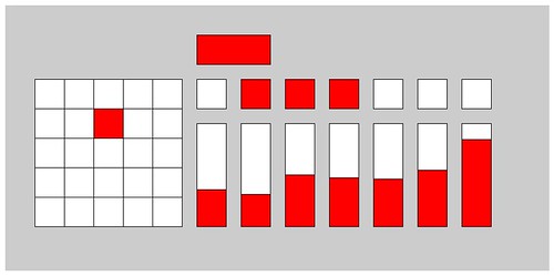
The process I used to create these sketches included the following steps: (1) creating the functionality associated to each element, separately; (2) creating a class for each element; (3) integrating objects of each class in Processing; (4) testing Processing with OSCulator and Ableton; (5) creating the Serial protocol to communicate the Arduino; (6) testing the sensors; (7) writing the final code for the Arduino; (8) testing Serial connection to Arduino; (9) calibration of the physical computing interface (whenever and wherever we set it up).
I have already made two posts on this subject (go to phase 1 post, go to phase 2 post), however, today I can attest that I have completed the vast majority of the work. The last processing sketch that I shared featured a mostly completed Matrix object that included functions for OSC communication. The serial communication protocol had also been defined.
The many additions to the sketch include creation of button and slider elements (each in its own class), a control panel (that holds the buttons and sliders), and a version of the application that features multiple button and sliders. The main updates to existing features include changes to Serial communication protocol to support additional sliders and matrices), and OSC communication code updates to ensure that messages are only sent when values change rather than continuously.
For the slider object I used the mouseDrag() function for the very first time. I had to debug my code for a while to get the visual slider to work properly. The button was easy to code from a visual perspective. The challenge I faced was in structuring the OSC messages so that I was able to send two separate and opposing messages for each click. The reason why this is important is that Ableton Live uses a separate buttons for starting and stopping clips. So I had to find a way to enable a single button to perform both functions.
The serial communication protocol update was easy to implement, so I will not delve into it here. To change the OSC communication protocol required a bit more work. I created a previous state variable in each object class to be enable verification of whether a change had occurred. The logic was implemented an “if” statement in the OSC message function.
Evolving the Controller
Here is an overview of my plans associated to this project: I plan to expand the current media controller with a few effect grids and the ability to select individual channels to apply effects. In order to do this I have to create new functions for the matrix class that enables me to set the X and Y matrix map values. I also want to work on improving the overall esthetics of the interface (while keeping its minimal feel).
From a sketch-architecture perspective I am considering creating a parent class for all buttons, grids and sliders. It would feature attributes and functionality that is common amongst all elements. Common attributes include location, size and color; common functionality requirements include detection of mouse location relative to object, OSC communication.
Questions for Class
Here is a question that came up during my development of this sketch (Dan, I need your help here). Can I use the translate, pop and pushMatrix commands to just to capture the current mouse location? This would be an easier solution to checking whether the mouse was hovering over an object.
In my previous post I already discussed the process for choosing the solution for playing and controlling our audio – we have decided to use Processing (and the Arduino) to control Ableton Live. Today I will provide an overview of how I developed the code for this application and some of the interface considerations associated to designing a software that could work across physical and screen-based interfaces.
My longer term objective is to create MIDI controllers using for audio and video applications using touchscreen and gestural interfaces. The interfaces that I am designing would ideally be evolved to work on multi-touch surfaces. In regards to my interest in gestural interaction, this I hope to explore through my current physical computing project and future projects.
Developing the Sketches
Since the physical computing project requires three basic types of controls that are the foundation of the media interface for my computational media mid-term, I decide to start with a focus on writing the code for these three basic elements. I set out to create code that could be easily re-used so that I could add additional elements with little effort. Here is a link to the sketch on openprocessing.org, where you can also view the full code for the controller pictured below (v1.0).
The process I used to create these sketches included the following steps: (1) creating the functionality associated to each element, separately; (2) creating a class for each element; (3) integrating objects of each class in Processing; (4) testing Processing with OSCulator and Ableton; (5) creating the Serial protocol to communicate the Arduino; (6) testing the sensors; (7) writing the final code for the Arduino; (8) testing Serial connection to Arduino; (9) calibration of the physical computing interface (whenever and wherever we set it up).
I have already made two posts on this subject (go to phase 1 post, go to phase 2 post), however, today I can attest that I have completed the vast majority of the work. The last processing sketch that I shared featured a mostly completed Matrix object that included functions for OSC communication. The serial communication protocol had also been defined.
The many additions to the sketch include creation of button and slider elements (each in its own class), a control panel (that holds the buttons and sliders), and a version of the application that features multiple button and sliders. The main updates to existing features include changes to Serial communication protocol to support additional sliders and matrices), and OSC communication code updates to ensure that messages are only sent when values change rather than continuously.
For the slider object I used the mouseDrag() function for the very first time. I had to debug my code for a while to get the visual slider to work properly. The button was easy to code from a visual perspective. The challenge I faced was in structuring the OSC messages so that I was able to send two separate and opposing messages for each click. The reason why this is important is that Ableton Live uses a separate buttons for starting and stopping clips. So I had to find a way to enable a single button to perform both functions.
The serial communication protocol update was easy to implement, so I will not delve into it here. To change the OSC communication protocol required a bit more work. I created a previous state variable in each object class to be enable verification of whether a change had occurred. The logic was implemented an “if” statement in the OSC message function.
Evolving the Controller
Here is an overview of my plans associated to this project: I plan to expand the current media controller with a few effect grids and the ability to select individual channels to apply effects. In order to do this I have to create new functions for the matrix class that enables me to set the X and Y matrix map values. I also want to work on improving the overall esthetics of the interface (while keeping its minimal feel).
From a sketch-architecture perspective I am considering creating a parent class for all buttons, grids and sliders. It would feature attributes and functionality that is common amongst all elements. Common attributes include location, size and color; common functionality requirements include detection of mouse location relative to object, OSC communication.
Questions for Class
Here is a question that came up during my development of this sketch (Dan, I need your help here). Can I use the translate, pop and pushMatrix commands to just to capture the current mouse location? This would be an easier solution to checking whether the mouse was hovering over an object.
Wednesday, October 28, 2009
Media Controller Project - Phase 2
This weekend I spent a lot of time working on solving the issue of how to control and manage the music clips that we want to use in our project. Our requirements are pretty straight forward, which is not to say easy to address.
Requirements for Audio Controls
We need a solution that can handle playback of looped samples and dynamic control of at least two effects to be applied on the sample (such as tempo and pitch). Ideally we would like the solution to be scalable (so we can add multiple sounds) and be able to support quantization and other techniques to ensure that the resulting sound is of good quality.
Since we are a creating a prototype to run off of a single computer we do not need this solution to be easily portable (e.g. it does not need to be easy to run on different computers).
Initial Assumptions
Due to the expertise of the team members we are using a combination of Arduino and Processing to do the heavy lifting in the areas of input sensing and data handling. After researching all of the options available in processing to manage sound, we have decided to use Ableton Live instead. Processing’s role will be relegated to interpreting the data from the Arduino to control Ableton Live via OSC.
Below I provide a more in-depth overview of my research and the solution that I have chosen. I have also posted an updated version of my sketch along with a link to the file I have created in Ableton Live for this application. Please note that you will need to set-up OSCulator in order for the sketch to work properly.
Latest Version of the Sketch
Note that I am only sharing the code for the sketch because no updates were made to the look, feel and interaction of the applet. All updates are related to enabling the sketch to communicate with Ableton via OSC.
Making Some Noise
When we started working on this project we assumed that we would be able to use one of Processing existing sound libraries to play and modulate an audio loop. However, after doing extensive research into Minim, ESS, and Sonia, I realized that none of these tools offered the feature set that we needed for this project.
The next solution that I investigated was Max/MSP. This programming language/environment is definitely capable of providing the functionality that we are looking for. However, no one on our team has the expertise to use it nor the time to learn it for this project.
using OSC to communicate with an external music application that can provide the features we are looking for. I was happy to find out that there is a simple library called oscP5 that makes it easy to communicate from a sketch using OSC. Equally important, I also found an application called OSCulator that routes and translates OSC and MIDI messages.
Having figured out how to get the sketch to communicate via OSC and MIDI we set out to find the right application. This was an easy task in large part because both Michael and I are familiar with Ableton.
I am happy to report that we already have Ableton up and running with the virtual matrix application developed in processing, though that is not to say the sketch is finished. We still need to add start and stop buttons to the interface, along with a volume control (not to mention other improvements and ideas that have not yet been considered).
In the next day or so I will share with you more updates, including details about how the physical elements of the interface are shaping up.
Requirements for Audio Controls
We need a solution that can handle playback of looped samples and dynamic control of at least two effects to be applied on the sample (such as tempo and pitch). Ideally we would like the solution to be scalable (so we can add multiple sounds) and be able to support quantization and other techniques to ensure that the resulting sound is of good quality.
Since we are a creating a prototype to run off of a single computer we do not need this solution to be easily portable (e.g. it does not need to be easy to run on different computers).
Initial Assumptions
Due to the expertise of the team members we are using a combination of Arduino and Processing to do the heavy lifting in the areas of input sensing and data handling. After researching all of the options available in processing to manage sound, we have decided to use Ableton Live instead. Processing’s role will be relegated to interpreting the data from the Arduino to control Ableton Live via OSC.
Below I provide a more in-depth overview of my research and the solution that I have chosen. I have also posted an updated version of my sketch along with a link to the file I have created in Ableton Live for this application. Please note that you will need to set-up OSCulator in order for the sketch to work properly.
Latest Version of the Sketch
Note that I am only sharing the code for the sketch because no updates were made to the look, feel and interaction of the applet. All updates are related to enabling the sketch to communicate with Ableton via OSC.
/* IPC Media Controller Project, October, 2009
 * VIRTUAL MATRIX SKETCH
 *
 * This sketch is the first draft of the processing portion of our media controller project
 * in its current state, this sketch only focuses on reading input from serial ports,
 * processing this input to determine location on the virtual matrix, then provide these
 * coordinates to other objects (such as the music generation object that we will create in the future)
 *
 */

import processing.serial.*;
Serial arduino;


import oscP5.*;
import netP5.*;
OscP5 oscComm;
NetAddress myRemoteLoc;

boolean isStarted = false;
// Matrix-Related Variables
Matrix matrix;
final int x = 0; final int y = 1;                                      // variables to use with matrix size array
int [] cellSize = {50, 50};
int [] screenPad = {25,25};                                       // define padding between grid and screen border
int [] screenSize = new int [2];                                  // define screen size, note that we only add volSize to width, since volume knob will be place to right of screen

// Volume-Control Related Variables
int [] volSize = {0,0};


void setup() {
   // initialize the matrix object
   matrix = new Matrix(screenPad[x], screenPad[y], cellSize[x], cellSize[y]);

   // instantiate the serial variable
   arduino = new Serial(this, Serial.list()[0], 9600);
   arduino.bufferUntil('.');

  // set frame rate
  frameRate(25);
  // start osc communication, listening for incoming messages at port 12000
  oscComm = new OscP5(this,12000);
  // set destination of our OSC messages (set to port 8000, which is the OSCulator port)
  myRemoteLoc = new NetAddress("10.0.1.3",8000);

   // set screen size related variables
   screenSize[y] = int(matrix.getMatrixWidth() + (screenPad[y] * 2));
   screenSize[x] = int(matrix.getMatrixHeight() + volSize[x] + (screenPad[Y]*2));
   size(screenSize[x], screenSize[y]);                             // draw the window 100 pixels wider and 50 pixels taller
}


void draw() {
  matrix.isCellActiveMouse();
  matrix.isCellActiveSerial();
  matrix.drawMatrix();
  matrix.sendOscMessage(oscComm, myRemoteLoc);
}


void serialEvent(Serial arduino) {
   matrix.readSerialInput(arduino);
}

void oscEvent(OscMessage theOscMessage) {
  /* print the address pattern and the typetag of the received OscMessage */
  print("### received an osc message.");
  print(" addrpattern: "+theOscMessage.addrPattern());
  println(" typetag: "+theOscMessage.typetag());
}


/* CLASS MATRIX
 *
 * this class holds a virtual matrix that will mimic the real world matrix.
 * It contains functions that read input from a serial port or mouse, then use that
 * input to determine the location of the object or mouse on the grid
 *
 */

class Matrix {

  // general variables used accross class
  final int x = 0; final int y = 1;                                      // variables to use with matrix size array
  final int mouseControl = 0; final int serialControl = 1;

  // matrix and cell related variables
  final int [] cellNumber = {5, 5};                                      // number of cells on the horizontal axis of the matrix
  final float [] cellSize = new float [2];                               // width and height of each cell of the matrix
  int [] matrixLoc = new int [2];                                        // location of the overall matrix
  final float [] matrixSize = new float [2];                             // the total height and width of the matrix
  float [] xCellLoc = new float [cellNumber[x]];                         // location of each cell on the grid
  float [] yCellLoc = new float [cellNumber[y]];                         // location of each cell on the grid
  Boolean [][] cellState = new Boolean [cellNumber[x]][cellNumber[y]];   // holds whether the mouse or serial object is hovering over a cell
  color activeColor = color (255,0,0);                                   // holds color of active cells
  color inactiveColor = color (255);                                     // holds color of inactive cells
  int [] previousState = {0,0};                                          // holds prevous state of the cell

  // variables for reading serial input
  int mainControl = mouseControl;
  float [] serialLoc = {0,0};                                            // holds Y reading from the serial port

  // Matrix Object Constructor
  Matrix (int XLoc, int YLoc, int cellWidth, int cellHeight) {
      matrixLoc[x] = XLoc;                                                    // set X and Y location of the virtual matrix
      matrixLoc[y] = YLoc;
      cellSize[x] = cellWidth;                                                // set the size of each cell on the grid of the virtual matrix
      cellSize[y] = cellHeight;
      matrixSize[x] = cellNumber[x] * cellSize[x];                            // calculate width of the matrix
      matrixSize[y] = cellNumber[y] * cellSize[y];                            // calculate height of the matrix

      // sets the location of each cell on the grid
      for (int xCounter = 0; xCounter < xCellLoc.length; xCounter++) {
            xCellLoc[xCounter] = xCounter * cellSize[x]; }
      for (int yCounter = 0; yCounter < yCellLoc.length; yCounter++){
            yCellLoc[yCounter] = yCounter * cellSize[y]; }

      // sets the status of each cell to false
      for (int xCounter = 0; xCounter < cellState.length; xCounter++) {
          for (int yCounter = 0; yCounter < cellState[xCounter].length; yCounter++) {
            cellState[xCounter][yCounter] = false; }
      }
  }  // close the constructor


 // function that returns the height of the matrix
 float getMatrixHeight(){
   return matrixSize[x];
 }


 // function that returns the width of the matrix
 float getMatrixWidth(){
   return matrixSize[y];
 }


 // function that draws the matrix on the screen
 void drawMatrix() {
   for (int xCounter = 0; xCounter < xCellLoc.length; xCounter++){                 // loop through each element in the xCellLoc array
       for (int yCounter = 0; yCounter < yCellLoc.length; yCounter++){             // loop through each element in the yCellLoc array
         if (cellState[xCounter][yCounter] == true) { fill(activeColor); }         // if the cellState is true then change the color of the cell
         else { fill(inactiveColor);}                                              // if the cellState is false then don't change the color of the cell
         rect(xCellLoc[xCounter]+matrixLoc[x], yCellLoc[yCounter]+matrixLoc[y], cellSize[x], cellSize[y]);    // draw rectangle
       }
   }
 }  // close drawMatrix() function


 // function that reads the input from the serial port
 void readSerialInput (Serial Arduino) {
   if (!isStarted) {                                                                 // if this is the first time we are establishing a connection
    isStarted = true;                                                                // set isStarted to true
    arduino.write("n");                                                              // respond to arduino to request more data
  } else {                                                                           // if this is NOT the first time we have received data from the arduino
    String bufferString = arduino.readString();                                      // read the buffer into the bufferString variable
    if (bufferString != null) {                                                      // if bufferString holds data then process the data
       bufferString = bufferString.substring(0, bufferString.length() - 1);             // trim the string
       String[] serialValues = splitTokens(bufferString, " ");                          // separate the two values from the string and save them in the serialValues variable
      serialLoc[x] = float(serialValues[x]);                                                  // assign value to serialLoc[x]
      serialLoc[y] = float(serialValues[y]);                                               // assign value to serialLoc[y]
    }
    arduino.write("n");                                                              // respond to arduino to request more data
  }
}  // close readSerialInput() function


// returns an array with the unfiltered x and y locations from the serial monitor (may need to filter data based on range of serial input and requirements of music objects)
int[] getSerialXY() {
  return int(serialLoc);
}

// TO BE CREATED
// function for user to set whether main input is serial or mouse based
void setMainControl(int tControlType) {
  mainControl = tControlType;
}

// function that sends OSC messages with input values
void sendOscMessage(OscP5 tOscComm, NetAddress tMyRemoteLoc) {
  float messageX = 0;
  float messageY = 0;

  // open new OSC messages of type x and type y
  OscMessage myOscXMessage = new OscMessage("/controlGrid/x");
  OscMessage myOscYMessage = new OscMessage("/controlGrid/y");

  // determine whether readings that are sent to OSC will originate from serial device or mouse
  if (mainControl == serialControl) {
    messageX = map(serialLoc[x], 0, width, 0, 1);
    messageY = map(serialLoc[y], 0, height, 0, 1);
  } else if (mainControl == mouseControl) {
    messageX = map(mouseX, 0, width, 0.075, 0.125);
    messageY = map(mouseY, 0, height, 0.3, 0.7);
  }

  myOscXMessage.add("x "); /* add an int to the osc message */
  myOscYMessage.add("y "); /* add an int to the osc message */
  myOscXMessage.add(messageX); /* add an int to the osc message */
  myOscYMessage.add(messageY); /* add a float to the osc message */
  tOscComm.send(myOscXMessage, tMyRemoteLoc);
  tOscComm.send(myOscYMessage, tMyRemoteLoc);

  print("X: " + messageX + " ");
  print("Y: " + messageY + " ");
  println();
}

// returns an array with the unfiltered x and y locations from the mouse-based interface (may need to filter data based on requirements of music object)
int [] getMmouseXY() {
   int [] mouseXY = {mouseX, mouseY};
   return mouseXY;
}


 // check if a cell on virtual Matrix is active based on the mouse location
 void isCellActiveMouse () {
  int XLocMouse = mouseX - matrixLoc[x];                                        // adjust variable to account for location of Matrix within window
  int YLocMouse = mouseY - matrixLoc[y];                                        // adjust variable to account for location of Matrix within window
  isCellActive(XLocMouse, YLocMouse);                                           // call the function to check if the cell is active based on current location of mouse
 }


 // check if a cell on virtual Matrix is active based on the current physical location/state of an external object
 void isCellActiveSerial () {
   int xLocSerial = int(map(serialLoc[x], 0, 1024, 0, matrixSize[x]));                // adjust variable to account for location of Matrix within window
   int yLocSerial = int(map(serialLoc[y], 0, 1024, 0, matrixSize[y]));                // adjust variable to account for location of Matrix within window
   isCellActive(xLocSerial, yLocSerial);                                        // call the function to check if the cell is active based on current location of mouse

 }


 // function that checks whether a specific cell is Active
 void isCellActive (int tXloc, int tYloc) {
  int xLoc = tXloc;                                                                  // set the location of the X coordinate where the mouse or serial object is located
  int yLoc = tYloc;                                                                  // set the location of the Y coordinate where the mouse or serial object is located

  for (int xCounter = 0; xCounter < xCellLoc.length; xCounter++){                     // loop through each element in the xCellLoc array
       for (int yCounter = 0; yCounter < yCellLoc.length; yCounter++){                // loop through each element in the yCellLoc array

           // check out what are the mouse or serial object is intersecting
           if (  (xLoc > xCellLoc[xCounter] && xLoc < (xCellLoc[xCounter] + cellSize[x])) &&
                 (yLoc > xCellLoc[yCounter] && yLoc < (yCellLoc[yCounter] + cellSize[y]))    ) {
                        cellState[previousState[x]][previousState[y]] = false;        // set previous grid element to false
                        cellState[xCounter][yCounter] = true;                         // set current element to active status
                        previousState[x] = xCounter;                                  // set x number of previous active cell
                        previousState[y] = yCounter;                                  // set y number of previous active cell
                 }
       }
  }
 }
}
Making Some Noise
When we started working on this project we assumed that we would be able to use one of Processing existing sound libraries to play and modulate an audio loop. However, after doing extensive research into Minim, ESS, and Sonia, I realized that none of these tools offered the feature set that we needed for this project.
The next solution that I investigated was Max/MSP. This programming language/environment is definitely capable of providing the functionality that we are looking for. However, no one on our team has the expertise to use it nor the time to learn it for this project.
using OSC to communicate with an external music application that can provide the features we are looking for. I was happy to find out that there is a simple library called oscP5 that makes it easy to communicate from a sketch using OSC. Equally important, I also found an application called OSCulator that routes and translates OSC and MIDI messages.
Having figured out how to get the sketch to communicate via OSC and MIDI we set out to find the right application. This was an easy task in large part because both Michael and I are familiar with Ableton.
I am happy to report that we already have Ableton up and running with the virtual matrix application developed in processing, though that is not to say the sketch is finished. We still need to add start and stop buttons to the interface, along with a volume control (not to mention other improvements and ideas that have not yet been considered).
In the next day or so I will share with you more updates, including details about how the physical elements of the interface are shaping up.
Monday, October 26, 2009
IPC Class Notes, Serial Communication P2 - Oct 21, 2009
Today’s class focused on expanding our understanding of serial communications and holding brief discussions regarding our media controller projects.
Media Controller Discussion – Specific Guidance
For our project one of the main areas that we have not yet solved is how to play and modulate the sound. In response to our request for input we briefly discussed the three sound libraries available in Processing:
Media Controller Discussion – General Guidance
Tom provided the class with an overview of a helpful process for building prototypes. Here is a description of it, along with some additional thoughts of my own. Once you’ve decided on the idea for your project and are ready to start building mental, virtual and physical prototypes it is useful to break down the idea into sensing, data processing and response activities.
When building out the sensing portion of your project, (1) if you have any doubts regarding whether your plan will work then you should create simple models to test your strategy. At this stage the simpler the better, though some times there is only so much simplification you can add.
Once you know that your overall sensing strategy is sound, (2) work on getting your sensors physically set-up and connected properly to the circuit. Test the circuit to ensure it works properly and confirm the range of the sensor.
(3) Only after confirming that the sensors are working properly should you move on to setting up communication between the Arduino and the computer (in our case, processing). There is nothing wrong with working on this section of the code simultaneously but just don’t try to debug your sensors from across the serial connection.
When working on the data processing part of your project, (1) start by focusing on developing a sketch that is able to process fake data before trying to connect the application to handle live sensor readings. (2) It can be helpful to develop a virtual version of your physical interface. It enables you to test code before the physical prototype is done, and can serve as a debugging tool. (3) Once the data processing is working, set-up and test the connection between the sensor, data processing, and response elements.
Follow a similar process for setting up the response mechanism. (1) Make sure that you can get it working on its own, (2) then connect it to the data processing hub (or directly to the Arduino) and test the two together.
Serial Communication - Part 2
To communicate multiple messages at once via the serial port requires use of one of the following strategies: (1) delimitation method; (2) handshaking.
(1) Delimitation (or Punctuation)
A communication protocol that leverages punctuation characters to demarcate where one piece of data begins and another one ends. Here is an overview of the Processing functions that you will need to use to decode the readings from the Arduino:
This protocol determines that the Arduino will not send any messages unless it receives a request from the computer. In order to make this protocol work you need to set-up the following logic to govern the communication cadence:
Miscellaneous Notes
Every time the serial port is opened the Arduino re-initiates the sketch that it is running.
Things to Check Out
Media Controller Discussion – Specific Guidance
For our project one of the main areas that we have not yet solved is how to play and modulate the sound. In response to our request for input we briefly discussed the three sound libraries available in Processing:
- Minim – sound generation and audio playback support with limited in functionality.
- ESS – more functionality then Minim but still very basic set of features.
- Sonia – most powerful, flexible and complex of the bunch.
Media Controller Discussion – General Guidance
Tom provided the class with an overview of a helpful process for building prototypes. Here is a description of it, along with some additional thoughts of my own. Once you’ve decided on the idea for your project and are ready to start building mental, virtual and physical prototypes it is useful to break down the idea into sensing, data processing and response activities.
When building out the sensing portion of your project, (1) if you have any doubts regarding whether your plan will work then you should create simple models to test your strategy. At this stage the simpler the better, though some times there is only so much simplification you can add.
Once you know that your overall sensing strategy is sound, (2) work on getting your sensors physically set-up and connected properly to the circuit. Test the circuit to ensure it works properly and confirm the range of the sensor.
(3) Only after confirming that the sensors are working properly should you move on to setting up communication between the Arduino and the computer (in our case, processing). There is nothing wrong with working on this section of the code simultaneously but just don’t try to debug your sensors from across the serial connection.
When working on the data processing part of your project, (1) start by focusing on developing a sketch that is able to process fake data before trying to connect the application to handle live sensor readings. (2) It can be helpful to develop a virtual version of your physical interface. It enables you to test code before the physical prototype is done, and can serve as a debugging tool. (3) Once the data processing is working, set-up and test the connection between the sensor, data processing, and response elements.
Follow a similar process for setting up the response mechanism. (1) Make sure that you can get it working on its own, (2) then connect it to the data processing hub (or directly to the Arduino) and test the two together.
Serial Communication - Part 2
To communicate multiple messages at once via the serial port requires use of one of the following strategies: (1) delimitation method; (2) handshaking.
(1) Delimitation (or Punctuation)
A communication protocol that leverages punctuation characters to demarcate where one piece of data begins and another one ends. Here is an overview of the Processing functions that you will need to use to decode the readings from the Arduino:
- PortName.bufferUntil() – sets on which character the serialEvent callback function is called by the serial buffer.
- String.Trim() – get rid of any blank space in the beginning and end of the string. Does not impact the middle of the string.
- Split(string, split character) – enables splitting the string at where ever the split character is found.
This protocol determines that the Arduino will not send any messages unless it receives a request from the computer. In order to make this protocol work you need to set-up the following logic to govern the communication cadence:
- On the Arduino sketch you need to integrate an if statement that confirms that data has been received via the serial port before it sends out any of its own data via the serial port (Serial.available() > 0). Make sure to clear the buffer every time by using the Serial.read() function. This if statement could also check for specific characters being received through the serial port.
- On the Processing side you need add code that sends out a message to the Arduino every time that Processing is ready to receive a new communication. This can be triggered anytime that Processing is done reading the current serial data buffer (or using counters and event-based triggers).
Miscellaneous Notes
Every time the serial port is opened the Arduino re-initiates the sketch that it is running.
- \n = new line
- \r = carriage return (goes back to the beginning of the line)
- Loop-based – processing and arduino are loop-based languages because at their core that organizes the code to run in a repetitive loop.
- Callback-based (event-based) – javascript on the other hand is a callback-based language that organizes codes to run based on events.
Things to Check Out
- Check out Dan’s site about the “rest of you” for information about bio-feedback.
- Look at Aaron’s theses on cats.
Subscribe to:
Posts (Atom)