Relays
Relays use inductance to enable small DC circuits to control larger DC or AC ones. Inductance refers to the phenomenon where electricity, which is running through a circuit, creates a magnetic field around the circuit.
Relays use these types of magnetic fields to close a physical switch that completes a larger circuit. The magnetic field is generated every time that electricity flows through the small load bearing circuit on the relay. From a physical perspective, a relay is essentially a coil that is wrapped around a reed switch. When electricity runs through the coil circuit it generates a magnetic fields that closes the switch.
Relays have at least 4 pins, 2 pins for the small circuit that generates the magnetic field, 2 pins for the larger circuit that is switched by the relay.
Due to the physical/mechanical nature of relay switches this solution can only support digital communications between circuits. The speed of the connection is also slow because. The main benefit of the relay is that you can control an AC current from a DC source.
Transistors
Transistors also enable small circuits to switch circuits with higher loads. Unlike the relays, these are non-mechanical switches. This means that they have a faster speed of reaction and are able to communicate analog data.
Transistors are made of different types of silicon. The arrangement of these silicon layers enable one lead, with a small current or voltage, to control the flow of electricity through two other leads, with larger current or voltage. If no electricity is provided to the controlling lead then no electricity will flow through the bigger circuit.
The leads on a transistor are referred to as: the base, which is connected to the microcontroller and accepts a small load, such as pulses from an output pin; the collector, which is connected to a higher voltage source; the emitter, which is connected to ground.
Motors and Solenoids
Motors work by having two magnets surrounded by coils. The electricity that goes through the motor creates an electric field that causes the magnets to spin. When the motor is turned off the magnets will continue to spin temporarily, this creates a current in the reverse direction.
When working with motors it is important to consider issues associated to its physicality and mechanical nature. First and foremost, the response time provide by motors differs considerably from electronic components such as LEDs. For example, to get a motor going it requires that sufficient power accumulate to overcome the initial inertia of the motor.
Motors create a reverse flow of electricity when they are stopping due to the phenomenon of inductance that is used to move the motors. This has some important repercussions when building circuits that include motors.
First, you often need to use diodes. As an example, when hooking up motors and transistors it is important to include a diode in circuits where a transistor is used to control a motor or solenoid. This diode is used to ensure that reverse electricity will not flow through the transistor, as this would ruin it. For this to work, the diode needs to enable electricity to flow in the direction from the emitter to the collector
Second, you need to use capacitors. Adding a capacitor between the voltage source and the microcontroller helps ensure that the microcontroller gets sufficient power, even if the motor reduces the overall amount of energy available in the circuit (as it does when it is first turned on is facing resistance). I encountered this problem when working on the motor movement lab earlier this week.
Controlling Motors
The direction in which a motor spins is controlled by the direction of the flow of electricity. To control motor direction we need to create a circuit that includes four transistors as outlined in the circuit diagram below.
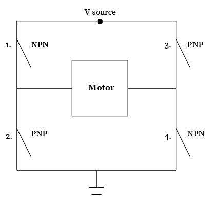
H-Bridges simplify the creation of circuits like the one above. They contain a network of transistors that enable the controlling of motor direction and speed. These components can support two separate motors, and have multiple input and output pins for each motor. Check out the diagram below from this week’s lab, it provides an overview of all pins on an H-Bridge.

No comments:
Post a Comment