Overview of the Project
The objective of our project was to create a media control surface that controls modulation and filtering of sound, and is compatible with existing music production applications. The physical interface is comprised of a square surface and a puck- or mouse-like object. The surface is like a two dimensional matrix, each dimension, or axis, of this matrix controls a specific filter or effect. The location of the object relative to each axis of the surface determines the level of the effects and filters.
I will soon add a video to this post that demonstrates our prototype in action along with some pictures from the build process.
In its current state we are able to mimic the functionality that we envisioned, though the system is not able to fully deliver the functionality on its own. We have fully figured out the software end of the application, however, work still needs to be done on the physical computing interface. More on that when I dive into the details of the design and build process for this device.
Building the Matrix Light Grid
Zeven was taking the lead on building the physical computing interface. I helped out in the design of the circuits for the LED lights, and the Arduino-based controller puck/mouse. Here is an overview of this process, our solution, and the issues that we still need to be resolved.
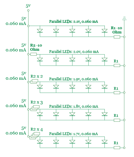
Our first attempt at setting-up the LED circuit was done without much thought. This resulted in the burn out of an entire row of LEDs. After this initial failure we decided to take the time to design the circuit and review the design with a resident before building and testing it. Here are the two designs that we reviewed, the first one was our preferred and chosen design.
Design Option 1 - Preferred and Selected
Design Option 2 - Considered
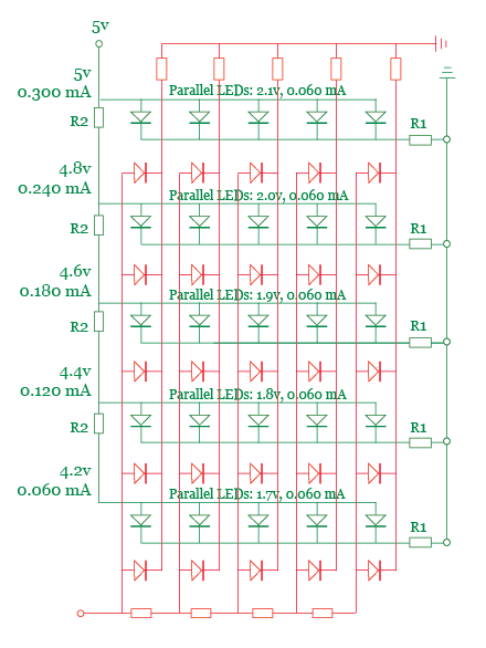
Once we agreed upon the design of the circuit we moved ahead with producing it. During the build process we used a multi-meter to check the amount of voltage being consumed by each row of LEDs. Based on my calculations I decided to use a resistor ladder with steps of 10 to 50 Ohms. The readings from the circuit confirmed our expectations, the increasing amount of resistance applied to each row in the circuit decreased the amount of voltage available to the LEDs on that row.
The next step in the build process involved setting up a test with a photocell to confirm that it was able to detect the variance in brightness of each row of LEDs. The initial tests were not successful, so we iterated through many rounds of other tests where we: added aluminum foil to increase the brightness of the lights, glued down the LEDs so that they are equal equidistant from the sensors, added a second photosensor to the controller object.
These changes helped us improve the quality of the sensor readings but they did not fully solve the problem. The final change that we made to the system was based on a suggestion from Tom. He recommended that, in order to improve the sensitivity of the system, we should use potentiometers to test different resistances for the sensor and LED circuits. We took this advice to heart and bought several 15-turn 1K mini-pots. These great little components helped us fine-tune the voltage of each LED row and the photosensors.
Unfortunately, this still did not fully solve our issues. The readings from the photosensors are not sufficiently consistent, even when smoothed via averaging. As an example, two LEDs that, connected in parallel on the same row and with the same amount of resistance, often gave different readings. This issue may be caused by the construction of each LED light box is not perfect, hence small amounts of light leakage may be responsible for the unexpected variances.
In the end our media controller works somewhat erratically due to the issues discussed above. Now I will dive into the software side of the mapping problem, determining how to map the readings from the controller to an appropriate MIDI message that can be delivered to Ableton.
Finalizing the Software
The core of the Arduino and Processing applications had been completed by the middle of last week. Therefore, our focus was on integrating the final physical interface with the multimedia computer and mapping readings from the serial port to appropriate MIDI messages.
Luckily, the integration process was quick and easy, unlike our attempts to map the readings from the photosensors. Due to the erratic values we received, we had to give up on our initial idea of using clear value ranges to determine which row and column of LEDs was being measured.
We were able to get the system to work partially by measuring the readings from each individual LED and then program a range based on that reading into the software. Unfortunately, due to light leakage and other potential contributors to our issue, we have not been able to achieve the resolution or smoothness that we hoped to.
Here is a link to the code from the final Processing and Arduino sketches.
Continuing to Improve the Interaction
Our original project idea was a more complex system that included several objects representing different instruments. Therefore, this is an obvious path that can be taken to increase the functionality of this prototype. However, before we consider extending the capabilities offered by this device we should examine how to solve the current implementation issues.
Two interesting ideas came up in class for solving the current issue with the system. Tom suggested that we add dark strips to the board. This would enable the photosensors to better detect movement of the controller. An accelorometer could be used to detect the direction of the movement, especially in a device where the controller’s orientation is pre-defined by a mechanism like the one that Zeven built.
The second suggestion came from Patrick. He asked whether we had considered using light filters coupled with multiple photosensors (e.g. having a photosensor for each color) to enable the system to better determine the location of the controller. I believe that these two approaches could be combined to improve the basic performance and increase the resolution offered by the system.
The final idea, which may hold the most potential, came to me as a result of examining another team’s media controller project. My inspiration came from a music sequencer that leverages switches designed as round holes, a conductive metal is visible on two opposite edges of each hole. In this design the switches are closed by the insertion of a metal ball in the round hole.
My vision is to build a surface comprised of similar round switches coupled with a controller that features small metal plates on the bottom. The controller would always close multiple switches at a time, thus providing an accurate mapping of its location to the system. The user would have the freedom to hold the controller in which ever direction they desire, assuming the proper designed can be created for the metal plates underneath the controller.
LED lights could be placed in the holes and used to display the current setting of the effects being controller. This would allow for the user to hot swap the effects being controlled by the unit, since the system would be able to communicate via the lights.
The one requirement (and reservation) I have about this design is how to make sure that the metal plates under the controller are always able to complete a circuit, while never mistakenly connecting two Ground or Voltage input pins.
1 comment:
Hi,
Good one on Media Controller Project - Phase 4.If you are into home business and searching for ways to build your business on a budget the this free video at http://debtfreeliving.buildingonabudget.com can help you.
Thanks,
Wilson.
Post a Comment