Resistor Ladders
Resistor ladders are electrical circuits that are referred to as ladders because they are made up of repeating units or resistors that create a ladder effect on the electrical current generated. The location of each component along the ladder determines the voltage that they are able to generate. The closer a switch is to the power source the higher the voltage that will flow through the circuit when that switch is opened. The Arduino is able to determine which element on the ladders is sending the input based on this shifting level of voltage provided.
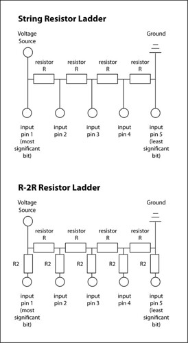 Here is a brief description of the two most common types of resistor ladders (for all I know these may be the only types). A string resistor ladder consists of a serial string of resistors. Between each resistor there is a connection to an input pin. The pin that is closest to the power source is called the most significant bit, while the farthest away is labeled the least significant bit. The R-2R resistor ladder differs from a standard string ladder in that it also features a second resistor with each switch.
Aside from enabling the Arduino to capture input from multiple switches using a single pin, resistor ladders are also often used for analog to digital conversion.
Multiplexing
Multiplexing is a second solution for expanding the number of input pins on the Arduino (demultiplexing is a solution for expanding outputs on the Arduino). One benefit of multiplexors is that they are able expand digital and analog inputs and outputs, unlike the ladder approach. Multiplexors are dedicated components that are required for multiplexing and demultiplexing.
Let’s explore the 4051 multiplexer, which is commonly used with the Arduino. Here is a link to the page regarding multiplexing on the Arduino . This component features 12 input/output pins. 4 of these pins are used to govern communications between the Arduino and the multiplexer, 3 of these pins are used to assign which pin is active, the remaining transfers the actual input or output data between the multiplexer and Arduino. The other 8 pins are the assignable pins that are used to connect other processors, sensors or actuators. Below is a schematic of the 4051 multiplexer.

Port Manipulation
While reading about the concepts described above I came across some interesting information about port manipulation on the Arduino. Over the past week I had come across several mentions of the ports on the Arduino in online examples and conversations at ITP. I am happy to report that I finally understand this capability.
The benefit of port manipulation is that it allows for lower-level and faster manipulation of the i/o pins of the microcontroller on an Arduino board. Here is a link to the page on the Arduino site that features more information about port manipulation.
The Arduino that runs an ATmega8 has the following three ports:
- B (digital pin 8 to 13)
- C (analog input pins)
- D (digital pins 0 to 7)
- DDR register: determines whether the pin is an INPUT or OUTPUT (read/write)
- PORT register: controls whether the pin is HIGH or LOW (read/write)
- PIN register: reads the state of INPUT pins set to input with pinMode() (read)
- Here is a DDR register example: “DDRD = B11110000;” this sets half of the pins as outputs (the ones set to 1) and the other half as inputs (the ones set to 0).
- Here is a PORT register example: “PORTD = B11111111;” this sets all of the pins to high on a given port.
No comments:
Post a Comment