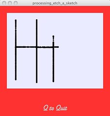
 To keep things simple, the lab exercise only requires that we set up a single analog input on the Arduino board – a potentiometer. This component is used to control a graph that is generated in processing and displayed on the monitor of the multimedia computer. I have decided to take this one step further, and to attempt to make a virtual etch-a-sketch.
Here is a link to the lab page where you can find the overview and code samples for the original lab. Another helpful link is this overview about Serial Communications from Tom Igoe’s blog. In regards to the etch-a-sketch, all of the Arduino code is included below, the processing code can be found here. But first, check out the quick video that I put together about this small project.
Managing the Communication
When communicating more than one piece of data it is important to create a syntax that can enable the receiving computer to parse out different commands.
I decide to use the following protocol for my messages to enable me to parse out the two readings from the potentiometers: The data from the first potentiometer would always be preceded by a period, while the data from the second would always be preceded by a space and followed by a period, which marked the beginning of the first data element. For example “.255 0.255 1.254 2.” And you get the point.
From the Arduino side, to make sure that I could read the serial input clearly I set the Serial.print() mode to DEC to transmit the information. Then, once the information was parsed on the other end I converted the values back to numbers (floats) so that I could use these values to determine the location of the drawing on the screen.
On the processing side I encounter more challenges than with the Arduino. The biggest problem that I had to solve was choosing a strategy for accurately reading the data from the serial port. At first I tried to read the input one character at a time, as outlined in the code sample below. I am sad to say that this approach did not work well enough because there was too much noise.
The Wrong Approach to Reading the Data
void serialEvent (Serial myPort) {
    // read the port
    readString = myPort.readChar();

    // if a period is found then set read the next characters as xPos values
    if (readString == char(46)) {
      readNow = "xPos";
      xPosString = "";

    // else if a space is found then set read the next characters as yPos values
    } else if (readString == char(32)) {
      readNow = "yPos";
      yPosString = "";

   // else if values have been set to be read as xPos
    } else if(readNow == "xPos") {
      if (xPosString == null) {xPosString = readString;}
      else { xPosString = xPosString + readString;}
       xPosString = xPosString + readString;

   // else if values have been set to be read as yPos
    } else if(readNow == "yPos") {
      if (yPosString == null) { yPosString = readString;}
      else {yPosString = yPosString + readString;}
       yPosString = yPosString + readString;
    }
}
I was able to get things working right by learning how to set Processing’s buffer size, which governs how many bytes are received before your application calls the serialEvent function. I set the buffer size to 20 and decided to capture one full string of 20 characters at a time. Then I proceeded to read just one set of readings from each of these buffer strings. This greatly stabilized the user experience.
Unfortunately, since potentiometers have a narrow rotation range it is not possible to create the true etch-a-sketch feeling with them. On screen you can use the arrow keys to draw – at ITP we will user the small controller pictured below to play around with this (at least for a couple of days until I decide to use these parts for my next little project).
Final Arduino Code
 int analogPin1 = 0;
 int analogPin2 = 1;
 int analogValue1 = 0;
 int analogValue2 = 0;

 void setup()
 {
   // start serial port at 9600 bps:
   Serial.begin(9600);
 }

 void loop()
 {
   // read analog inputs:
   analogValue1 = analogRead(analogPin1);
   analogValue2 = analogRead(analogPin2);

   // reduce range to appropriate range for analog output by dividing by 4
   analogValue1 = analogValue1 / 4;
   analogValue2 = analogValue2 / 4;

   // print values to serial port
   Serial.print(analogValue1, DEC);
   Serial.print(" ");
   Serial.print(analogValue2, DEC);
   Serial.print(".");

   delay(5 );
 }
No comments:
Post a Comment