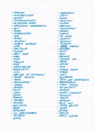
Earlier today I worked with Arturo, Eric, and Tamar to develop the concept and storyboards for our Communication Lab class. We met up this morning at eleven in a coffee shop near the ITP floor. After brainstorming for 30 minutes we created a long list of possible inspirations for our story. Here is a link to a more readable version of this document.
After developing this list we identified a few main themes and explored many different storylines. We settled on the idea of creating a video that captures a news program host going ballistic. We were loosely inspired by Bill O'Reilly's famous freakout - I can't believe that I am admitting to being inspired by Mr. O'Reilly.
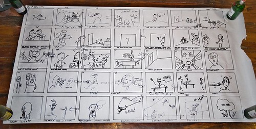
After developing the general arch of the story we headed back to the ITP floor to collaboratively draw the storyboards on the large rolls of paper from the studio. Here is a picture of our finished work (follow this link to view a more readable version).
Monday, November 9, 2009
Friday, November 6, 2009
ICM Class Notes - Using PHP - November 5, 2009
In today’s ICM class we reviewed basic concepts associated to PHP, and discussed when to use PHP (as a stand alone solution, or in conjunction with Processing).
PHP – Hypertext Pre-Processor Language
PHP was designed for server-side scripting – for development of applications that run on servers. In contrast, Processing (and Java on which it is built) was developed for client side applications – for development of programs that run on client-side computers. Originally designed to serve dynamic web content. In short, PHP enables us to store and capture information from a server more effectively and efficiently than Processing.
Here is an example of an application where PHP is used to store data for a Processing sketch. This code was written by Dan Shiffman, my professor at ITP, and it features a shared white board, where users can add new coordinates that can be viewed by all other users (anyone can also clear the board). PHP can also be used to develop a multi-user high score feature for a game developed in Processing.
How to Run PHP?
In order to run PHP you need a server or computer that is properly set-up. Most web servers support PHP, though the ones that are based on Microsoft solutions tend not to. That said, even servers that support PHP need to be properly set-up. Luckily for us, the ITP server is already set up for PHP. Many desktop and laptop computers can also be set-up to run PHP scripts.
PHP code is usually embedded in HTML documents. To embed PHP code into an HTML document the following identifiers are used: “” ends a code block. It is important to note that PHP code will not be present on the HTML source available via web browers. The reason being, the PHP code on the server is used to dynamically generate the HTML code that is sent to your computer, and viewable as source.
The Basic Elements of Coding – PHP Style
The basic concepts associated to PHP coding are similar to those used in Processing. PHP is an object-oriented language that features all of the same attributes: variables, conditionals, loops, functions, classes, etc. Here is a quick overview of some basic similarities and differences between these two tools.
Primitive Variables
All variables in PHP need to be defined/initiated by being assigned a value. To identify a variable the variable name needs to be preceded by the “$” character. However, unlike Processing, PHP does not require or support the typing of variables. This is a more flexible approach than Processing but it also opens the doors to more mistakes not being caught by the compiler.
Example variable definition code: “$ x = 5;”
Arrays
To make an array in PHP you just assign an “array(arrayElements)” to any variable name. As with primitive variables, there is no need to define the array type. To add elements to an array is simple simpler than in Processing, as shown below. It is important to note a PHP array can also hold different types of data.
- Creating an array: “$arraySample = array(0,1,2,3);”
- Adding an element to an array: “$arraySample[] = 5;”
PHP also supports associative arrays as well. These arrays indentify each data element by a name as opposed to an index number. These arrays can be used in interesting ways. They are available in Processing through Java.
- Using an associative array: “$arraySample[“fred”] = 50;”
Conditionals and Loops
The syntax for loops and conditional statements is identical to that found in Processing.
Functions and OOP in PHP
In PHP to define a function it name needs to be preceded by the identifier “function”. Similar to variables definitions, functions are not typed. Class definitions feature the same overall structure, though the constructor name is identified as “function _constructor()”. When working with instances of objects the “->” in PHP replaces the “.” in Processing.
Query Strings
Query string refers to HTML urls that reference PHP scripts and contain information that can be processed by the PHP script to dynamically generate content (HTML or other text-based documents). Since PHP primarily runs on web servers, this is the main way in which information is passed to PHP scripts. Here is an example where the identifier “name” contains data element “Julio”, “nationality” contains “brazil”, and “residence” contains “nyc”.
“http://……sample.php?name=Julio&nationality=brazil&residence=nyc”
Online, these query strings are most often used to transmit data captured from users via a web forms. Processing applications can generate query scripts that both request data and initiate other activities on the server side.
Reading Query Strings
To read values from query strings an associative array is used. PHP creates an associative array that pairs each identifier from the query string (which is always consistent) with a data element (which is variable). This array is called $_GET. Here is a sample line of code to read my name from the query string above into the variable $name:
“$name =$_GET[“name”];”
PHP Resources
Miscellaneous
- Dan shared with us Coda, a development environment that enables programmers to access and edit PHP and HTML files on the server. Coda is a text editor and ftp application combined in one.
- In today’s class we got to see Josh K’s project, a sketch that generates a line that evolves in a 3D space using the principles of Perlin noise. It is a great looking visual, unfortunately, he has not yet posted the sketch online.
Media Controller Project - Phase 4
Yesterday we finalized and presented our media controller project for Introduction to Physical Computing class. Here I will share a video of the final working (or at least mostly working) prototype, then provide an overview of the building process for the physical interface, and go over some of the final updates made to the processing and arduino code. I will wrap up this post by sharing some ideas on how to evolve this device so that I could deliver on its full potential.
Overview of the Project
The objective of our project was to create a media control surface that controls modulation and filtering of sound, and is compatible with existing music production applications. The physical interface is comprised of a square surface and a puck- or mouse-like object. The surface is like a two dimensional matrix, each dimension, or axis, of this matrix controls a specific filter or effect. The location of the object relative to each axis of the surface determines the level of the effects and filters.
I will soon add a video to this post that demonstrates our prototype in action along with some pictures from the build process.
In its current state we are able to mimic the functionality that we envisioned, though the system is not able to fully deliver the functionality on its own. We have fully figured out the software end of the application, however, work still needs to be done on the physical computing interface. More on that when I dive into the details of the design and build process for this device.
Building the Matrix Light Grid
Zeven was taking the lead on building the physical computing interface. I helped out in the design of the circuits for the LED lights, and the Arduino-based controller puck/mouse. Here is an overview of this process, our solution, and the issues that we still need to be resolved.
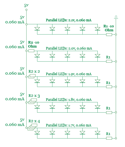
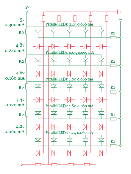
Our first attempt at setting-up the LED circuit was done without much thought. This resulted in the burn out of an entire row of LEDs. After this initial failure we decided to take the time to design the circuit and review the design with a resident before building and testing it. Here are the two designs that we reviewed, the first one was our preferred and chosen design.
Design Option 1 - Preferred and Selected
Design Option 2 - Considered
Once we agreed upon the design of the circuit we moved ahead with producing it. During the build process we used a multi-meter to check the amount of voltage being consumed by each row of LEDs. Based on my calculations I decided to use a resistor ladder with steps of 10 to 50 Ohms. The readings from the circuit confirmed our expectations, the increasing amount of resistance applied to each row in the circuit decreased the amount of voltage available to the LEDs on that row.
The next step in the build process involved setting up a test with a photocell to confirm that it was able to detect the variance in brightness of each row of LEDs. The initial tests were not successful, so we iterated through many rounds of other tests where we: added aluminum foil to increase the brightness of the lights, glued down the LEDs so that they are equal equidistant from the sensors, added a second photosensor to the controller object.
These changes helped us improve the quality of the sensor readings but they did not fully solve the problem. The final change that we made to the system was based on a suggestion from Tom. He recommended that, in order to improve the sensitivity of the system, we should use potentiometers to test different resistances for the sensor and LED circuits. We took this advice to heart and bought several 15-turn 1K mini-pots. These great little components helped us fine-tune the voltage of each LED row and the photosensors.
Unfortunately, this still did not fully solve our issues. The readings from the photosensors are not sufficiently consistent, even when smoothed via averaging. As an example, two LEDs that, connected in parallel on the same row and with the same amount of resistance, often gave different readings. This issue may be caused by the construction of each LED light box is not perfect, hence small amounts of light leakage may be responsible for the unexpected variances.
In the end our media controller works somewhat erratically due to the issues discussed above. Now I will dive into the software side of the mapping problem, determining how to map the readings from the controller to an appropriate MIDI message that can be delivered to Ableton.
Finalizing the Software
The core of the Arduino and Processing applications had been completed by the middle of last week. Therefore, our focus was on integrating the final physical interface with the multimedia computer and mapping readings from the serial port to appropriate MIDI messages.
Luckily, the integration process was quick and easy, unlike our attempts to map the readings from the photosensors. Due to the erratic values we received, we had to give up on our initial idea of using clear value ranges to determine which row and column of LEDs was being measured.
We were able to get the system to work partially by measuring the readings from each individual LED and then program a range based on that reading into the software. Unfortunately, due to light leakage and other potential contributors to our issue, we have not been able to achieve the resolution or smoothness that we hoped to.
Here is a link to the code from the final Processing and Arduino sketches.
Continuing to Improve the Interaction
Our original project idea was a more complex system that included several objects representing different instruments. Therefore, this is an obvious path that can be taken to increase the functionality of this prototype. However, before we consider extending the capabilities offered by this device we should examine how to solve the current implementation issues.
Two interesting ideas came up in class for solving the current issue with the system. Tom suggested that we add dark strips to the board. This would enable the photosensors to better detect movement of the controller. An accelorometer could be used to detect the direction of the movement, especially in a device where the controller’s orientation is pre-defined by a mechanism like the one that Zeven built.
The second suggestion came from Patrick. He asked whether we had considered using light filters coupled with multiple photosensors (e.g. having a photosensor for each color) to enable the system to better determine the location of the controller. I believe that these two approaches could be combined to improve the basic performance and increase the resolution offered by the system.
The final idea, which may hold the most potential, came to me as a result of examining another team’s media controller project. My inspiration came from a music sequencer that leverages switches designed as round holes, a conductive metal is visible on two opposite edges of each hole. In this design the switches are closed by the insertion of a metal ball in the round hole.
My vision is to build a surface comprised of similar round switches coupled with a controller that features small metal plates on the bottom. The controller would always close multiple switches at a time, thus providing an accurate mapping of its location to the system. The user would have the freedom to hold the controller in which ever direction they desire, assuming the proper designed can be created for the metal plates underneath the controller.
LED lights could be placed in the holes and used to display the current setting of the effects being controller. This would allow for the user to hot swap the effects being controlled by the unit, since the system would be able to communicate via the lights.
The one requirement (and reservation) I have about this design is how to make sure that the metal plates under the controller are always able to complete a circuit, while never mistakenly connecting two Ground or Voltage input pins.
Overview of the Project
The objective of our project was to create a media control surface that controls modulation and filtering of sound, and is compatible with existing music production applications. The physical interface is comprised of a square surface and a puck- or mouse-like object. The surface is like a two dimensional matrix, each dimension, or axis, of this matrix controls a specific filter or effect. The location of the object relative to each axis of the surface determines the level of the effects and filters.
I will soon add a video to this post that demonstrates our prototype in action along with some pictures from the build process.
In its current state we are able to mimic the functionality that we envisioned, though the system is not able to fully deliver the functionality on its own. We have fully figured out the software end of the application, however, work still needs to be done on the physical computing interface. More on that when I dive into the details of the design and build process for this device.
Building the Matrix Light Grid
Zeven was taking the lead on building the physical computing interface. I helped out in the design of the circuits for the LED lights, and the Arduino-based controller puck/mouse. Here is an overview of this process, our solution, and the issues that we still need to be resolved.
Our first attempt at setting-up the LED circuit was done without much thought. This resulted in the burn out of an entire row of LEDs. After this initial failure we decided to take the time to design the circuit and review the design with a resident before building and testing it. Here are the two designs that we reviewed, the first one was our preferred and chosen design.
Design Option 1 - Preferred and Selected
Design Option 2 - Considered
Once we agreed upon the design of the circuit we moved ahead with producing it. During the build process we used a multi-meter to check the amount of voltage being consumed by each row of LEDs. Based on my calculations I decided to use a resistor ladder with steps of 10 to 50 Ohms. The readings from the circuit confirmed our expectations, the increasing amount of resistance applied to each row in the circuit decreased the amount of voltage available to the LEDs on that row.
The next step in the build process involved setting up a test with a photocell to confirm that it was able to detect the variance in brightness of each row of LEDs. The initial tests were not successful, so we iterated through many rounds of other tests where we: added aluminum foil to increase the brightness of the lights, glued down the LEDs so that they are equal equidistant from the sensors, added a second photosensor to the controller object.
These changes helped us improve the quality of the sensor readings but they did not fully solve the problem. The final change that we made to the system was based on a suggestion from Tom. He recommended that, in order to improve the sensitivity of the system, we should use potentiometers to test different resistances for the sensor and LED circuits. We took this advice to heart and bought several 15-turn 1K mini-pots. These great little components helped us fine-tune the voltage of each LED row and the photosensors.
Unfortunately, this still did not fully solve our issues. The readings from the photosensors are not sufficiently consistent, even when smoothed via averaging. As an example, two LEDs that, connected in parallel on the same row and with the same amount of resistance, often gave different readings. This issue may be caused by the construction of each LED light box is not perfect, hence small amounts of light leakage may be responsible for the unexpected variances.
In the end our media controller works somewhat erratically due to the issues discussed above. Now I will dive into the software side of the mapping problem, determining how to map the readings from the controller to an appropriate MIDI message that can be delivered to Ableton.
Finalizing the Software
The core of the Arduino and Processing applications had been completed by the middle of last week. Therefore, our focus was on integrating the final physical interface with the multimedia computer and mapping readings from the serial port to appropriate MIDI messages.
Luckily, the integration process was quick and easy, unlike our attempts to map the readings from the photosensors. Due to the erratic values we received, we had to give up on our initial idea of using clear value ranges to determine which row and column of LEDs was being measured.
We were able to get the system to work partially by measuring the readings from each individual LED and then program a range based on that reading into the software. Unfortunately, due to light leakage and other potential contributors to our issue, we have not been able to achieve the resolution or smoothness that we hoped to.
Here is a link to the code from the final Processing and Arduino sketches.
Continuing to Improve the Interaction
Our original project idea was a more complex system that included several objects representing different instruments. Therefore, this is an obvious path that can be taken to increase the functionality of this prototype. However, before we consider extending the capabilities offered by this device we should examine how to solve the current implementation issues.
Two interesting ideas came up in class for solving the current issue with the system. Tom suggested that we add dark strips to the board. This would enable the photosensors to better detect movement of the controller. An accelorometer could be used to detect the direction of the movement, especially in a device where the controller’s orientation is pre-defined by a mechanism like the one that Zeven built.
The second suggestion came from Patrick. He asked whether we had considered using light filters coupled with multiple photosensors (e.g. having a photosensor for each color) to enable the system to better determine the location of the controller. I believe that these two approaches could be combined to improve the basic performance and increase the resolution offered by the system.
The final idea, which may hold the most potential, came to me as a result of examining another team’s media controller project. My inspiration came from a music sequencer that leverages switches designed as round holes, a conductive metal is visible on two opposite edges of each hole. In this design the switches are closed by the insertion of a metal ball in the round hole.
My vision is to build a surface comprised of similar round switches coupled with a controller that features small metal plates on the bottom. The controller would always close multiple switches at a time, thus providing an accurate mapping of its location to the system. The user would have the freedom to hold the controller in which ever direction they desire, assuming the proper designed can be created for the metal plates underneath the controller.
LED lights could be placed in the holes and used to display the current setting of the effects being controller. This would allow for the user to hot swap the effects being controlled by the unit, since the system would be able to communicate via the lights.
The one requirement (and reservation) I have about this design is how to make sure that the metal plates under the controller are always able to complete a circuit, while never mistakenly connecting two Ground or Voltage input pins.
Friday, October 30, 2009
ICM Class Notes - Using Images and Video - October 22, 2009
Here are my notes from last week’s ICM class, where we learned how to use pictures and video in Processing. It’s taken me some time for me to get around to posting these notes because I have been focused on developing the media controller for physical computing, and working on my mid-term project. Without further ado here are my notes.
Using Images in Processing
There are two main types of activities related to using and manipulating pictures in Processing:
1. Loading and displaying images
2. Reading and manipulating the pixels
Loading and Displaying Images
In processing there is a class that handles images that is called PImage - in many ways this class is similar to the PFont object. For example, to create a new instance of an image object the loadImage(URL) function is used rather than a “new” object declaration. Here is sample code:
PFont cat;
cat = loadImage(“cat.jpg”);
The image() function is used to draw onto the screen images that are loaded. This method requires from 3 to 5 arguments, here is the complete set: image(PImageVar, xpos, ypos, width [optional], height [optional]). We can assign an image to the background() function as well, in which case the image would be displayed as the background. Here are some useful methods associated to displaying images:
Loading and Displaying Videos
Processing handles videos in the same way that it handles images (it actually views videos as a bunch of standalone images. Using live video in processing is done through the Capture class. To use this class you need to add the video library to your sketch. Note that you need to use a different class to include movies, which are pre-recorded videos. Unfortunately, Processing does a bad job at handling movies though it works well with live video feeds.
To declare a Capture object you need to use the standard “new” object declaration: “myVideo = new Capture(this, xpos, ypos, refresh rate)”. When you initiate a video object processing will default to using the default system camera. The name of an alternate video source can be added between the ypos and refresh rate variables.
Before you display an image you need to read the image using the myVideo.read() function. The same image() that is used for PImage objects will display images from the camera onto the screen. All of the image processing functions discussed above can also be used to analyze video input.
Using Images in Processing
There are two main types of activities related to using and manipulating pictures in Processing:
1. Loading and displaying images
2. Reading and manipulating the pixels
Loading and Displaying Images
In processing there is a class that handles images that is called PImage - in many ways this class is similar to the PFont object. For example, to create a new instance of an image object the loadImage(URL) function is used rather than a “new” object declaration. Here is sample code:
PFont cat;
cat = loadImage(“cat.jpg”);
The image() function is used to draw onto the screen images that are loaded. This method requires from 3 to 5 arguments, here is the complete set: image(PImageVar, xpos, ypos, width [optional], height [optional]). We can assign an image to the background() function as well, in which case the image would be displayed as the background. Here are some useful methods associated to displaying images:
- The imageMode() function allows setting of image alignment. Setting options include CENTER, CORNER (standard setting) and CORNERS.
- The tint() function enables changing the color of the image. It does not color the picture but rather removes the other colors. So if you change the tint to red, processing will set all G and B value to “0”. Tint also supports setting the transparency of an image.
- The PImage.get(xpos, ypos) function returns the color from the pixel at the coordinate xpos ypos. Get() can be used without an image to get the color of the pixel at coordinates xpos and ypos of the processing screen.
- The PImage.set(xpos, ypos, color) function sets the pixel at location xpos ypos to the color that is passed as the third argument.
- The red(color) (green() and blue()) functions determines how of that color (red, green or blue) is included in that pixels.
Loading and Displaying Videos
Processing handles videos in the same way that it handles images (it actually views videos as a bunch of standalone images. Using live video in processing is done through the Capture class. To use this class you need to add the video library to your sketch. Note that you need to use a different class to include movies, which are pre-recorded videos. Unfortunately, Processing does a bad job at handling movies though it works well with live video feeds.
To declare a Capture object you need to use the standard “new” object declaration: “myVideo = new Capture(this, xpos, ypos, refresh rate)”. When you initiate a video object processing will default to using the default system camera. The name of an alternate video source can be added between the ypos and refresh rate variables.
Before you display an image you need to read the image using the myVideo.read() function. The same image() that is used for PImage objects will display images from the camera onto the screen. All of the image processing functions discussed above can also be used to analyze video input.
Media Controller Project (and ICM Mid Term) - Phase 3
During that last several days I have been working on setting up a Processing sketch that can work with my Physical Computing media controller and serve as my mid-term project for the Introduction to Computational Media course. Long before arriving at ITP I have been interested in the design and development of media controllers. This project provided the opportunity for me to start some hands-on explorations.
In my previous post I already discussed the process for choosing the solution for playing and controlling our audio – we have decided to use Processing (and the Arduino) to control Ableton Live. Today I will provide an overview of how I developed the code for this application and some of the interface considerations associated to designing a software that could work across physical and screen-based interfaces.
My longer term objective is to create MIDI controllers using for audio and video applications using touchscreen and gestural interfaces. The interfaces that I am designing would ideally be evolved to work on multi-touch surfaces. In regards to my interest in gestural interaction, this I hope to explore through my current physical computing project and future projects.
Developing the Sketches
Since the physical computing project requires three basic types of controls that are the foundation of the media interface for my computational media mid-term, I decide to start with a focus on writing the code for these three basic elements. I set out to create code that could be easily re-used so that I could add additional elements with little effort. Here is a link to the sketch on openprocessing.org, where you can also view the full code for the controller pictured below (v1.0).
The process I used to create these sketches included the following steps: (1) creating the functionality associated to each element, separately; (2) creating a class for each element; (3) integrating objects of each class in Processing; (4) testing Processing with OSCulator and Ableton; (5) creating the Serial protocol to communicate the Arduino; (6) testing the sensors; (7) writing the final code for the Arduino; (8) testing Serial connection to Arduino; (9) calibration of the physical computing interface (whenever and wherever we set it up).
I have already made two posts on this subject (go to phase 1 post, go to phase 2 post), however, today I can attest that I have completed the vast majority of the work. The last processing sketch that I shared featured a mostly completed Matrix object that included functions for OSC communication. The serial communication protocol had also been defined.
The many additions to the sketch include creation of button and slider elements (each in its own class), a control panel (that holds the buttons and sliders), and a version of the application that features multiple button and sliders. The main updates to existing features include changes to Serial communication protocol to support additional sliders and matrices), and OSC communication code updates to ensure that messages are only sent when values change rather than continuously.
For the slider object I used the mouseDrag() function for the very first time. I had to debug my code for a while to get the visual slider to work properly. The button was easy to code from a visual perspective. The challenge I faced was in structuring the OSC messages so that I was able to send two separate and opposing messages for each click. The reason why this is important is that Ableton Live uses a separate buttons for starting and stopping clips. So I had to find a way to enable a single button to perform both functions.
The serial communication protocol update was easy to implement, so I will not delve into it here. To change the OSC communication protocol required a bit more work. I created a previous state variable in each object class to be enable verification of whether a change had occurred. The logic was implemented an “if” statement in the OSC message function.
Evolving the Controller
Here is an overview of my plans associated to this project: I plan to expand the current media controller with a few effect grids and the ability to select individual channels to apply effects. In order to do this I have to create new functions for the matrix class that enables me to set the X and Y matrix map values. I also want to work on improving the overall esthetics of the interface (while keeping its minimal feel).
From a sketch-architecture perspective I am considering creating a parent class for all buttons, grids and sliders. It would feature attributes and functionality that is common amongst all elements. Common attributes include location, size and color; common functionality requirements include detection of mouse location relative to object, OSC communication.
Questions for Class
Here is a question that came up during my development of this sketch (Dan, I need your help here). Can I use the translate, pop and pushMatrix commands to just to capture the current mouse location? This would be an easier solution to checking whether the mouse was hovering over an object.
In my previous post I already discussed the process for choosing the solution for playing and controlling our audio – we have decided to use Processing (and the Arduino) to control Ableton Live. Today I will provide an overview of how I developed the code for this application and some of the interface considerations associated to designing a software that could work across physical and screen-based interfaces.
My longer term objective is to create MIDI controllers using for audio and video applications using touchscreen and gestural interfaces. The interfaces that I am designing would ideally be evolved to work on multi-touch surfaces. In regards to my interest in gestural interaction, this I hope to explore through my current physical computing project and future projects.
Developing the Sketches
Since the physical computing project requires three basic types of controls that are the foundation of the media interface for my computational media mid-term, I decide to start with a focus on writing the code for these three basic elements. I set out to create code that could be easily re-used so that I could add additional elements with little effort. Here is a link to the sketch on openprocessing.org, where you can also view the full code for the controller pictured below (v1.0).
The process I used to create these sketches included the following steps: (1) creating the functionality associated to each element, separately; (2) creating a class for each element; (3) integrating objects of each class in Processing; (4) testing Processing with OSCulator and Ableton; (5) creating the Serial protocol to communicate the Arduino; (6) testing the sensors; (7) writing the final code for the Arduino; (8) testing Serial connection to Arduino; (9) calibration of the physical computing interface (whenever and wherever we set it up).
I have already made two posts on this subject (go to phase 1 post, go to phase 2 post), however, today I can attest that I have completed the vast majority of the work. The last processing sketch that I shared featured a mostly completed Matrix object that included functions for OSC communication. The serial communication protocol had also been defined.
The many additions to the sketch include creation of button and slider elements (each in its own class), a control panel (that holds the buttons and sliders), and a version of the application that features multiple button and sliders. The main updates to existing features include changes to Serial communication protocol to support additional sliders and matrices), and OSC communication code updates to ensure that messages are only sent when values change rather than continuously.
For the slider object I used the mouseDrag() function for the very first time. I had to debug my code for a while to get the visual slider to work properly. The button was easy to code from a visual perspective. The challenge I faced was in structuring the OSC messages so that I was able to send two separate and opposing messages for each click. The reason why this is important is that Ableton Live uses a separate buttons for starting and stopping clips. So I had to find a way to enable a single button to perform both functions.
The serial communication protocol update was easy to implement, so I will not delve into it here. To change the OSC communication protocol required a bit more work. I created a previous state variable in each object class to be enable verification of whether a change had occurred. The logic was implemented an “if” statement in the OSC message function.
Evolving the Controller
Here is an overview of my plans associated to this project: I plan to expand the current media controller with a few effect grids and the ability to select individual channels to apply effects. In order to do this I have to create new functions for the matrix class that enables me to set the X and Y matrix map values. I also want to work on improving the overall esthetics of the interface (while keeping its minimal feel).
From a sketch-architecture perspective I am considering creating a parent class for all buttons, grids and sliders. It would feature attributes and functionality that is common amongst all elements. Common attributes include location, size and color; common functionality requirements include detection of mouse location relative to object, OSC communication.
Questions for Class
Here is a question that came up during my development of this sketch (Dan, I need your help here). Can I use the translate, pop and pushMatrix commands to just to capture the current mouse location? This would be an easier solution to checking whether the mouse was hovering over an object.
Wednesday, October 28, 2009
Media Controller Project - Phase 2
This weekend I spent a lot of time working on solving the issue of how to control and manage the music clips that we want to use in our project. Our requirements are pretty straight forward, which is not to say easy to address.
Requirements for Audio Controls
We need a solution that can handle playback of looped samples and dynamic control of at least two effects to be applied on the sample (such as tempo and pitch). Ideally we would like the solution to be scalable (so we can add multiple sounds) and be able to support quantization and other techniques to ensure that the resulting sound is of good quality.
Since we are a creating a prototype to run off of a single computer we do not need this solution to be easily portable (e.g. it does not need to be easy to run on different computers).
Initial Assumptions
Due to the expertise of the team members we are using a combination of Arduino and Processing to do the heavy lifting in the areas of input sensing and data handling. After researching all of the options available in processing to manage sound, we have decided to use Ableton Live instead. Processing’s role will be relegated to interpreting the data from the Arduino to control Ableton Live via OSC.
Below I provide a more in-depth overview of my research and the solution that I have chosen. I have also posted an updated version of my sketch along with a link to the file I have created in Ableton Live for this application. Please note that you will need to set-up OSCulator in order for the sketch to work properly.
Latest Version of the Sketch
Note that I am only sharing the code for the sketch because no updates were made to the look, feel and interaction of the applet. All updates are related to enabling the sketch to communicate with Ableton via OSC.
Making Some Noise
When we started working on this project we assumed that we would be able to use one of Processing existing sound libraries to play and modulate an audio loop. However, after doing extensive research into Minim, ESS, and Sonia, I realized that none of these tools offered the feature set that we needed for this project.
The next solution that I investigated was Max/MSP. This programming language/environment is definitely capable of providing the functionality that we are looking for. However, no one on our team has the expertise to use it nor the time to learn it for this project.
using OSC to communicate with an external music application that can provide the features we are looking for. I was happy to find out that there is a simple library called oscP5 that makes it easy to communicate from a sketch using OSC. Equally important, I also found an application called OSCulator that routes and translates OSC and MIDI messages.
Having figured out how to get the sketch to communicate via OSC and MIDI we set out to find the right application. This was an easy task in large part because both Michael and I are familiar with Ableton.
I am happy to report that we already have Ableton up and running with the virtual matrix application developed in processing, though that is not to say the sketch is finished. We still need to add start and stop buttons to the interface, along with a volume control (not to mention other improvements and ideas that have not yet been considered).
In the next day or so I will share with you more updates, including details about how the physical elements of the interface are shaping up.
Requirements for Audio Controls
We need a solution that can handle playback of looped samples and dynamic control of at least two effects to be applied on the sample (such as tempo and pitch). Ideally we would like the solution to be scalable (so we can add multiple sounds) and be able to support quantization and other techniques to ensure that the resulting sound is of good quality.
Since we are a creating a prototype to run off of a single computer we do not need this solution to be easily portable (e.g. it does not need to be easy to run on different computers).
Initial Assumptions
Due to the expertise of the team members we are using a combination of Arduino and Processing to do the heavy lifting in the areas of input sensing and data handling. After researching all of the options available in processing to manage sound, we have decided to use Ableton Live instead. Processing’s role will be relegated to interpreting the data from the Arduino to control Ableton Live via OSC.
Below I provide a more in-depth overview of my research and the solution that I have chosen. I have also posted an updated version of my sketch along with a link to the file I have created in Ableton Live for this application. Please note that you will need to set-up OSCulator in order for the sketch to work properly.
Latest Version of the Sketch
Note that I am only sharing the code for the sketch because no updates were made to the look, feel and interaction of the applet. All updates are related to enabling the sketch to communicate with Ableton via OSC.
/* IPC Media Controller Project, October, 2009
* VIRTUAL MATRIX SKETCH
*
* This sketch is the first draft of the processing portion of our media controller project
* in its current state, this sketch only focuses on reading input from serial ports,
* processing this input to determine location on the virtual matrix, then provide these
* coordinates to other objects (such as the music generation object that we will create in the future)
*
*/
import processing.serial.*;
Serial arduino;
import oscP5.*;
import netP5.*;
OscP5 oscComm;
NetAddress myRemoteLoc;
boolean isStarted = false;
// Matrix-Related Variables
Matrix matrix;
final int x = 0; final int y = 1; // variables to use with matrix size array
int [] cellSize = {50, 50};
int [] screenPad = {25,25}; // define padding between grid and screen border
int [] screenSize = new int [2]; // define screen size, note that we only add volSize to width, since volume knob will be place to right of screen
// Volume-Control Related Variables
int [] volSize = {0,0};
void setup() {
// initialize the matrix object
matrix = new Matrix(screenPad[x], screenPad[y], cellSize[x], cellSize[y]);
// instantiate the serial variable
arduino = new Serial(this, Serial.list()[0], 9600);
arduino.bufferUntil('.');
// set frame rate
frameRate(25);
// start osc communication, listening for incoming messages at port 12000
oscComm = new OscP5(this,12000);
// set destination of our OSC messages (set to port 8000, which is the OSCulator port)
myRemoteLoc = new NetAddress("10.0.1.3",8000);
// set screen size related variables
screenSize[y] = int(matrix.getMatrixWidth() + (screenPad[y] * 2));
screenSize[x] = int(matrix.getMatrixHeight() + volSize[x] + (screenPad[Y]*2));
size(screenSize[x], screenSize[y]); // draw the window 100 pixels wider and 50 pixels taller
}
void draw() {
matrix.isCellActiveMouse();
matrix.isCellActiveSerial();
matrix.drawMatrix();
matrix.sendOscMessage(oscComm, myRemoteLoc);
}
void serialEvent(Serial arduino) {
matrix.readSerialInput(arduino);
}
void oscEvent(OscMessage theOscMessage) {
/* print the address pattern and the typetag of the received OscMessage */
print("### received an osc message.");
print(" addrpattern: "+theOscMessage.addrPattern());
println(" typetag: "+theOscMessage.typetag());
}
/* CLASS MATRIX
*
* this class holds a virtual matrix that will mimic the real world matrix.
* It contains functions that read input from a serial port or mouse, then use that
* input to determine the location of the object or mouse on the grid
*
*/
class Matrix {
// general variables used accross class
final int x = 0; final int y = 1; // variables to use with matrix size array
final int mouseControl = 0; final int serialControl = 1;
// matrix and cell related variables
final int [] cellNumber = {5, 5}; // number of cells on the horizontal axis of the matrix
final float [] cellSize = new float [2]; // width and height of each cell of the matrix
int [] matrixLoc = new int [2]; // location of the overall matrix
final float [] matrixSize = new float [2]; // the total height and width of the matrix
float [] xCellLoc = new float [cellNumber[x]]; // location of each cell on the grid
float [] yCellLoc = new float [cellNumber[y]]; // location of each cell on the grid
Boolean [][] cellState = new Boolean [cellNumber[x]][cellNumber[y]]; // holds whether the mouse or serial object is hovering over a cell
color activeColor = color (255,0,0); // holds color of active cells
color inactiveColor = color (255); // holds color of inactive cells
int [] previousState = {0,0}; // holds prevous state of the cell
// variables for reading serial input
int mainControl = mouseControl;
float [] serialLoc = {0,0}; // holds Y reading from the serial port
// Matrix Object Constructor
Matrix (int XLoc, int YLoc, int cellWidth, int cellHeight) {
matrixLoc[x] = XLoc; // set X and Y location of the virtual matrix
matrixLoc[y] = YLoc;
cellSize[x] = cellWidth; // set the size of each cell on the grid of the virtual matrix
cellSize[y] = cellHeight;
matrixSize[x] = cellNumber[x] * cellSize[x]; // calculate width of the matrix
matrixSize[y] = cellNumber[y] * cellSize[y]; // calculate height of the matrix
// sets the location of each cell on the grid
for (int xCounter = 0; xCounter < xCellLoc.length; xCounter++) {
xCellLoc[xCounter] = xCounter * cellSize[x]; }
for (int yCounter = 0; yCounter < yCellLoc.length; yCounter++){
yCellLoc[yCounter] = yCounter * cellSize[y]; }
// sets the status of each cell to false
for (int xCounter = 0; xCounter < cellState.length; xCounter++) {
for (int yCounter = 0; yCounter < cellState[xCounter].length; yCounter++) {
cellState[xCounter][yCounter] = false; }
}
} // close the constructor
// function that returns the height of the matrix
float getMatrixHeight(){
return matrixSize[x];
}
// function that returns the width of the matrix
float getMatrixWidth(){
return matrixSize[y];
}
// function that draws the matrix on the screen
void drawMatrix() {
for (int xCounter = 0; xCounter < xCellLoc.length; xCounter++){ // loop through each element in the xCellLoc array
for (int yCounter = 0; yCounter < yCellLoc.length; yCounter++){ // loop through each element in the yCellLoc array
if (cellState[xCounter][yCounter] == true) { fill(activeColor); } // if the cellState is true then change the color of the cell
else { fill(inactiveColor);} // if the cellState is false then don't change the color of the cell
rect(xCellLoc[xCounter]+matrixLoc[x], yCellLoc[yCounter]+matrixLoc[y], cellSize[x], cellSize[y]); // draw rectangle
}
}
} // close drawMatrix() function
// function that reads the input from the serial port
void readSerialInput (Serial Arduino) {
if (!isStarted) { // if this is the first time we are establishing a connection
isStarted = true; // set isStarted to true
arduino.write("n"); // respond to arduino to request more data
} else { // if this is NOT the first time we have received data from the arduino
String bufferString = arduino.readString(); // read the buffer into the bufferString variable
if (bufferString != null) { // if bufferString holds data then process the data
bufferString = bufferString.substring(0, bufferString.length() - 1); // trim the string
String[] serialValues = splitTokens(bufferString, " "); // separate the two values from the string and save them in the serialValues variable
serialLoc[x] = float(serialValues[x]); // assign value to serialLoc[x]
serialLoc[y] = float(serialValues[y]); // assign value to serialLoc[y]
}
arduino.write("n"); // respond to arduino to request more data
}
} // close readSerialInput() function
// returns an array with the unfiltered x and y locations from the serial monitor (may need to filter data based on range of serial input and requirements of music objects)
int[] getSerialXY() {
return int(serialLoc);
}
// TO BE CREATED
// function for user to set whether main input is serial or mouse based
void setMainControl(int tControlType) {
mainControl = tControlType;
}
// function that sends OSC messages with input values
void sendOscMessage(OscP5 tOscComm, NetAddress tMyRemoteLoc) {
float messageX = 0;
float messageY = 0;
// open new OSC messages of type x and type y
OscMessage myOscXMessage = new OscMessage("/controlGrid/x");
OscMessage myOscYMessage = new OscMessage("/controlGrid/y");
// determine whether readings that are sent to OSC will originate from serial device or mouse
if (mainControl == serialControl) {
messageX = map(serialLoc[x], 0, width, 0, 1);
messageY = map(serialLoc[y], 0, height, 0, 1);
} else if (mainControl == mouseControl) {
messageX = map(mouseX, 0, width, 0.075, 0.125);
messageY = map(mouseY, 0, height, 0.3, 0.7);
}
myOscXMessage.add("x "); /* add an int to the osc message */
myOscYMessage.add("y "); /* add an int to the osc message */
myOscXMessage.add(messageX); /* add an int to the osc message */
myOscYMessage.add(messageY); /* add a float to the osc message */
tOscComm.send(myOscXMessage, tMyRemoteLoc);
tOscComm.send(myOscYMessage, tMyRemoteLoc);
print("X: " + messageX + " ");
print("Y: " + messageY + " ");
println();
}
// returns an array with the unfiltered x and y locations from the mouse-based interface (may need to filter data based on requirements of music object)
int [] getMmouseXY() {
int [] mouseXY = {mouseX, mouseY};
return mouseXY;
}
// check if a cell on virtual Matrix is active based on the mouse location
void isCellActiveMouse () {
int XLocMouse = mouseX - matrixLoc[x]; // adjust variable to account for location of Matrix within window
int YLocMouse = mouseY - matrixLoc[y]; // adjust variable to account for location of Matrix within window
isCellActive(XLocMouse, YLocMouse); // call the function to check if the cell is active based on current location of mouse
}
// check if a cell on virtual Matrix is active based on the current physical location/state of an external object
void isCellActiveSerial () {
int xLocSerial = int(map(serialLoc[x], 0, 1024, 0, matrixSize[x])); // adjust variable to account for location of Matrix within window
int yLocSerial = int(map(serialLoc[y], 0, 1024, 0, matrixSize[y])); // adjust variable to account for location of Matrix within window
isCellActive(xLocSerial, yLocSerial); // call the function to check if the cell is active based on current location of mouse
}
// function that checks whether a specific cell is Active
void isCellActive (int tXloc, int tYloc) {
int xLoc = tXloc; // set the location of the X coordinate where the mouse or serial object is located
int yLoc = tYloc; // set the location of the Y coordinate where the mouse or serial object is located
for (int xCounter = 0; xCounter < xCellLoc.length; xCounter++){ // loop through each element in the xCellLoc array
for (int yCounter = 0; yCounter < yCellLoc.length; yCounter++){ // loop through each element in the yCellLoc array
// check out what are the mouse or serial object is intersecting
if ( (xLoc > xCellLoc[xCounter] && xLoc < (xCellLoc[xCounter] + cellSize[x])) &&
(yLoc > xCellLoc[yCounter] && yLoc < (yCellLoc[yCounter] + cellSize[y])) ) {
cellState[previousState[x]][previousState[y]] = false; // set previous grid element to false
cellState[xCounter][yCounter] = true; // set current element to active status
previousState[x] = xCounter; // set x number of previous active cell
previousState[y] = yCounter; // set y number of previous active cell
}
}
}
}
}
Making Some Noise
When we started working on this project we assumed that we would be able to use one of Processing existing sound libraries to play and modulate an audio loop. However, after doing extensive research into Minim, ESS, and Sonia, I realized that none of these tools offered the feature set that we needed for this project.
The next solution that I investigated was Max/MSP. This programming language/environment is definitely capable of providing the functionality that we are looking for. However, no one on our team has the expertise to use it nor the time to learn it for this project.
using OSC to communicate with an external music application that can provide the features we are looking for. I was happy to find out that there is a simple library called oscP5 that makes it easy to communicate from a sketch using OSC. Equally important, I also found an application called OSCulator that routes and translates OSC and MIDI messages.
Having figured out how to get the sketch to communicate via OSC and MIDI we set out to find the right application. This was an easy task in large part because both Michael and I are familiar with Ableton.
I am happy to report that we already have Ableton up and running with the virtual matrix application developed in processing, though that is not to say the sketch is finished. We still need to add start and stop buttons to the interface, along with a volume control (not to mention other improvements and ideas that have not yet been considered).
In the next day or so I will share with you more updates, including details about how the physical elements of the interface are shaping up.
Monday, October 26, 2009
IPC Class Notes, Serial Communication P2 - Oct 21, 2009
Today’s class focused on expanding our understanding of serial communications and holding brief discussions regarding our media controller projects.
Media Controller Discussion – Specific Guidance
For our project one of the main areas that we have not yet solved is how to play and modulate the sound. In response to our request for input we briefly discussed the three sound libraries available in Processing:
Media Controller Discussion – General Guidance
Tom provided the class with an overview of a helpful process for building prototypes. Here is a description of it, along with some additional thoughts of my own. Once you’ve decided on the idea for your project and are ready to start building mental, virtual and physical prototypes it is useful to break down the idea into sensing, data processing and response activities.
When building out the sensing portion of your project, (1) if you have any doubts regarding whether your plan will work then you should create simple models to test your strategy. At this stage the simpler the better, though some times there is only so much simplification you can add.
Once you know that your overall sensing strategy is sound, (2) work on getting your sensors physically set-up and connected properly to the circuit. Test the circuit to ensure it works properly and confirm the range of the sensor.
(3) Only after confirming that the sensors are working properly should you move on to setting up communication between the Arduino and the computer (in our case, processing). There is nothing wrong with working on this section of the code simultaneously but just don’t try to debug your sensors from across the serial connection.
When working on the data processing part of your project, (1) start by focusing on developing a sketch that is able to process fake data before trying to connect the application to handle live sensor readings. (2) It can be helpful to develop a virtual version of your physical interface. It enables you to test code before the physical prototype is done, and can serve as a debugging tool. (3) Once the data processing is working, set-up and test the connection between the sensor, data processing, and response elements.
Follow a similar process for setting up the response mechanism. (1) Make sure that you can get it working on its own, (2) then connect it to the data processing hub (or directly to the Arduino) and test the two together.
Serial Communication - Part 2
To communicate multiple messages at once via the serial port requires use of one of the following strategies: (1) delimitation method; (2) handshaking.
(1) Delimitation (or Punctuation)
A communication protocol that leverages punctuation characters to demarcate where one piece of data begins and another one ends. Here is an overview of the Processing functions that you will need to use to decode the readings from the Arduino:
This protocol determines that the Arduino will not send any messages unless it receives a request from the computer. In order to make this protocol work you need to set-up the following logic to govern the communication cadence:
Miscellaneous Notes
Every time the serial port is opened the Arduino re-initiates the sketch that it is running.
Things to Check Out
Media Controller Discussion – Specific Guidance
For our project one of the main areas that we have not yet solved is how to play and modulate the sound. In response to our request for input we briefly discussed the three sound libraries available in Processing:
- Minim – sound generation and audio playback support with limited in functionality.
- ESS – more functionality then Minim but still very basic set of features.
- Sonia – most powerful, flexible and complex of the bunch.
Media Controller Discussion – General Guidance
Tom provided the class with an overview of a helpful process for building prototypes. Here is a description of it, along with some additional thoughts of my own. Once you’ve decided on the idea for your project and are ready to start building mental, virtual and physical prototypes it is useful to break down the idea into sensing, data processing and response activities.
When building out the sensing portion of your project, (1) if you have any doubts regarding whether your plan will work then you should create simple models to test your strategy. At this stage the simpler the better, though some times there is only so much simplification you can add.
Once you know that your overall sensing strategy is sound, (2) work on getting your sensors physically set-up and connected properly to the circuit. Test the circuit to ensure it works properly and confirm the range of the sensor.
(3) Only after confirming that the sensors are working properly should you move on to setting up communication between the Arduino and the computer (in our case, processing). There is nothing wrong with working on this section of the code simultaneously but just don’t try to debug your sensors from across the serial connection.
When working on the data processing part of your project, (1) start by focusing on developing a sketch that is able to process fake data before trying to connect the application to handle live sensor readings. (2) It can be helpful to develop a virtual version of your physical interface. It enables you to test code before the physical prototype is done, and can serve as a debugging tool. (3) Once the data processing is working, set-up and test the connection between the sensor, data processing, and response elements.
Follow a similar process for setting up the response mechanism. (1) Make sure that you can get it working on its own, (2) then connect it to the data processing hub (or directly to the Arduino) and test the two together.
Serial Communication - Part 2
To communicate multiple messages at once via the serial port requires use of one of the following strategies: (1) delimitation method; (2) handshaking.
(1) Delimitation (or Punctuation)
A communication protocol that leverages punctuation characters to demarcate where one piece of data begins and another one ends. Here is an overview of the Processing functions that you will need to use to decode the readings from the Arduino:
- PortName.bufferUntil() – sets on which character the serialEvent callback function is called by the serial buffer.
- String.Trim() – get rid of any blank space in the beginning and end of the string. Does not impact the middle of the string.
- Split(string, split character) – enables splitting the string at where ever the split character is found.
This protocol determines that the Arduino will not send any messages unless it receives a request from the computer. In order to make this protocol work you need to set-up the following logic to govern the communication cadence:
- On the Arduino sketch you need to integrate an if statement that confirms that data has been received via the serial port before it sends out any of its own data via the serial port (Serial.available() > 0). Make sure to clear the buffer every time by using the Serial.read() function. This if statement could also check for specific characters being received through the serial port.
- On the Processing side you need add code that sends out a message to the Arduino every time that Processing is ready to receive a new communication. This can be triggered anytime that Processing is done reading the current serial data buffer (or using counters and event-based triggers).
Miscellaneous Notes
Every time the serial port is opened the Arduino re-initiates the sketch that it is running.
- \n = new line
- \r = carriage return (goes back to the beginning of the line)
- Loop-based – processing and arduino are loop-based languages because at their core that organizes the code to run in a repetitive loop.
- Callback-based (event-based) – javascript on the other hand is a callback-based language that organizes codes to run based on events.
Things to Check Out
- Check out Dan’s site about the “rest of you” for information about bio-feedback.
- Look at Aaron’s theses on cats.
Thursday, October 22, 2009
ICM Class Notes on Text Processing and Serial - Oct 14, 2009
Last week’s ICM class focused on parsing strings, picking up where we left off the week before, with a short overview of serial communications. Here a list of the topics that we covered:
XML has a hierarchical structure similar to a tree. This makes XML files easier to read than other types of content. There are many different ways that you can read XML documents in processing. Here is an overview of these options:
This week we were introduced to the concept of tokens and splits. Tokens are small chunks of text (these are only one character long). Here is a list of functions that leverage tokens or splits.
There are two main approaches to creating protocols for serial communication. The first is called punctuation, and it entails adding tokens to the data being communicated to enable the receiving computer to parse the data once received. The second approach, called handshaking, entails having each computer wait to send a message until they have received data from the other connected device.
I will not review these approaches here in detail because I have covered them in my posts from the Intro to Physical Computing class. The punctuation method is described here. I will soon add a link to the post regarding the handshake method (which is currently a work in progress).
Related notes and concepts:
- Processing and XML
- Additional functions for processing text
- Serial communications
XML has a hierarchical structure similar to a tree. This makes XML files easier to read than other types of content. There are many different ways that you can read XML documents in processing. Here is an overview of these options:
- Standard string parsing functions in processing, like the ones outlined below and in my post from last week.
- Existing processing XML libraries. Examples of these include simpleML, XMLElement, proXML. The libraries enable processing to navigate the structure of an XML file by finding a data elements by navigating through its children or parent structure.
- Application processing interfaces (APIs) from the data source. Examples of sites with APIs include Flickr, Google Maps, etc.
This week we were introduced to the concept of tokens and splits. Tokens are small chunks of text (these are only one character long). Here is a list of functions that leverage tokens or splits.
- split(String, SplitStringIdentifier); – This function returns multiple strings. The input copy “String” is split at the instance(s) of SplitStringidentifier. The SplitStringIdentifier is removed from the final strings.
- splitTokens(s, multiple SplitStringIdentifier); – This function is the same of split, however, it can accept multiple SplitStringIdentifiers. These are input all together within quotation marks. For example using “_.” Would look for instances where either “_” or “.” appear in the string.
- equals(); – This function compares the copy contained in a string to a piece of text data. For example “string.equals(“stringData”);” is equivalent to the syntax “intVar == 3”. That said, we cannot use the Boolean operator “==” to match strings. That is why the equals() function is needed. In order to compare words regardless of whether they are lower or upper case we can use the string.toLowerCase() function.
- Regular Expressions - Regular expressions are special text strings for describing search patterns. These capabilities enable more sophisticated parsing of content than is possible through the standard functionality in Processing. This is the ideal way to perform complex data parsing and cleaning. We did not cover this in class, so research will be needed on this front.
There are two main approaches to creating protocols for serial communication. The first is called punctuation, and it entails adding tokens to the data being communicated to enable the receiving computer to parse the data once received. The second approach, called handshaking, entails having each computer wait to send a message until they have received data from the other connected device.
I will not review these approaches here in detail because I have covered them in my posts from the Intro to Physical Computing class. The punctuation method is described here. I will soon add a link to the post regarding the handshake method (which is currently a work in progress).
Related notes and concepts:
- CallBack refer to methods that are called by other applications when a certain event takes place. MousePressed and SerialEvent are types of callback or event functions available in processing.
- To create a new serial object it is important to always include the Serial library (as it is not a standard processing library). Then to instantiate the object, once you’ve declared it, you need to use the following syntax: “portName = new Serial(this, “serialPortNumber”, baudRate);” The “this” argumen tells the serial object that it is setting up a communication between the serial port and this specific sketch.
Serial Communication Lab, Sending Multiple Bits of Data
Late last night I completed this week's lab for Introduction to Physical Computing class. Our focus this week was on expanding our ability to leverage serial communications to enable a computer and microcontroller to send and interpret multiple pieces of data to each other at any given time. The key challenge involved in this process is setting-up a protocol that can be encoded by the sender and interpreted by the receiver. Here is a link to the instructions for this lab.
We specifically focused on exploring two different approaches for this type of communication: (1) punctuation protocols; (2) handshake (or polite communication) protocols. I will not delve into these in detail here because I will soon post my full notes from this week's class that will cover this topics in greater length. Here is the video from this week's lab:
I am happy to report that I did not encounter any issues with either of these approaches. My previous experience setting up this type of communications was a great help. (here are some links to the previous projects and labs where I had already explored these types of serial communications: Fangs Controller; Etch-a-Sketch; Media Controller.)
That is not to say that I did not learn from this week's lab. For example, the "establishContact()" function on the Arduino easily solves a problem that I struggled with yesterday when building the first draft of the media controller project "middleware". Also, though I have been able to leverage this type of functionality previously, I am still a novice in need of much reinforcement as provided by this lab.
We specifically focused on exploring two different approaches for this type of communication: (1) punctuation protocols; (2) handshake (or polite communication) protocols. I will not delve into these in detail here because I will soon post my full notes from this week's class that will cover this topics in greater length. Here is the video from this week's lab:
I am happy to report that I did not encounter any issues with either of these approaches. My previous experience setting up this type of communications was a great help. (here are some links to the previous projects and labs where I had already explored these types of serial communications: Fangs Controller; Etch-a-Sketch; Media Controller.)
That is not to say that I did not learn from this week's lab. For example, the "establishContact()" function on the Arduino easily solves a problem that I struggled with yesterday when building the first draft of the media controller project "middleware". Also, though I have been able to leverage this type of functionality previously, I am still a novice in need of much reinforcement as provided by this lab.
Wednesday, October 21, 2009
Media Controller Project - Phase I
I recently began to work on a media controller project with two colleagues from ITP, Zeven Rodriguez and Michael Martinez-Campos. After much discussion, and our fair share of agreements and disagreements we have decided to develop an interface for music modulation. This device is going to be composed of a square horizontal surface coupled with a physical mouse-like object. By sliding the object across the surface, a user is able to modulate two attributes of the sound that is being generated.
Ideally, we would like to make the axis of this surface assignable (e.g. you could choose the effect/modulation associated to each axis). Also, it would be great if we could provide the user with the ability to play multiple sounds simultaneously, and to choose whether to control all sounds, or just a single sound with this surface.
That said, this project is being developed as part of our Introduction to Physical Computing curriculum. For our initial deadline 2-weeks from now we have decided to keep things simple; if we get things done sooner we may try to integrate some of these features.
To help get things done efficiently we have divided our roles and responsibilities. Zeven is taking the lead on creating the physical surface and object. Mike is working on investigating the solutions for the sound generation through Processing. I am leading the development of what I am calling the middleware - the application that gets the data from the sensors and feeds it to the program that will generate the music.
Creating the Connection (and a Virtual Grid/Surface)
Earlier today I finished the initial version of the processing application that will be responsible for reading data from the serial port, interpreting that data, and sending it onto to the sound generator. This is an important step in the evolution of this project, though I know that many updates will have to be made to this app during the coming weeks.
Pictures of Arduino Input for Test
One of the biggest challenges in creating this sketch was setting up the serial communication between the Arduino and Processing - we need to find a way to send data from two sensors to the computer. We decided to use the handshake protocol because it minimizes response delays.
Since I just learned how to use this type of protocol, it took me a little bit to get it working properly. Below I’ve included a brief overview of the issues I encountered along with the code I wrote for the Arduino, and a link to the Processing application.
Using the Handshake Communication Protocol
To set-up the handshake protocol, the first thing I did was to create a syntax for the communications. Unfortunately, that syntax did not work so I had to update it a few times to smooth out all of the kinks. Below I have shared the original and revised protocols.
Once I understood the problem it was easy to fix. The solution was to add an “if” statement to check whether a piece data received by the computer is the first piece of data in the communication stream. I noticed that the code sample from this week’s labs features a similar solution.
Processing Sketch
Here is a link to the processing sketch that I developed (please note that I've commented out all serial communications related functionality in order for this sketch to run online). Below you will find the code for the Arduino.
Code for the Arduino
Ideally, we would like to make the axis of this surface assignable (e.g. you could choose the effect/modulation associated to each axis). Also, it would be great if we could provide the user with the ability to play multiple sounds simultaneously, and to choose whether to control all sounds, or just a single sound with this surface.
That said, this project is being developed as part of our Introduction to Physical Computing curriculum. For our initial deadline 2-weeks from now we have decided to keep things simple; if we get things done sooner we may try to integrate some of these features.
To help get things done efficiently we have divided our roles and responsibilities. Zeven is taking the lead on creating the physical surface and object. Mike is working on investigating the solutions for the sound generation through Processing. I am leading the development of what I am calling the middleware - the application that gets the data from the sensors and feeds it to the program that will generate the music.
Creating the Connection (and a Virtual Grid/Surface)
Earlier today I finished the initial version of the processing application that will be responsible for reading data from the serial port, interpreting that data, and sending it onto to the sound generator. This is an important step in the evolution of this project, though I know that many updates will have to be made to this app during the coming weeks.
Pictures of Arduino Input for Test
One of the biggest challenges in creating this sketch was setting up the serial communication between the Arduino and Processing - we need to find a way to send data from two sensors to the computer. We decided to use the handshake protocol because it minimizes response delays.
Since I just learned how to use this type of protocol, it took me a little bit to get it working properly. Below I’ve included a brief overview of the issues I encountered along with the code I wrote for the Arduino, and a link to the Processing application.
Using the Handshake Communication Protocol
To set-up the handshake protocol, the first thing I did was to create a syntax for the communications. Unfortunately, that syntax did not work so I had to update it a few times to smooth out all of the kinks. Below I have shared the original and revised protocols.
- Initial protocol: “valueOne.valueTwo. \n\r” (e.g. “224.200.\n\r”). The new line and carriage return characters are appended by the println() function that I used to send data for the my first attempts.
- Final protocol: “valueOne valueTwo.” (e.g. “224 200.”). After numerous frustrating attempts to get the initial protocol to work, I decided to simplify the protocol as outlined above.
Once I understood the problem it was easy to fix. The solution was to add an “if” statement to check whether a piece data received by the computer is the first piece of data in the communication stream. I noticed that the code sample from this week’s labs features a similar solution.
Processing Sketch
Here is a link to the processing sketch that I developed (please note that I've commented out all serial communications related functionality in order for this sketch to run online). Below you will find the code for the Arduino.
Code for the Arduino
int analogPin1 = 0;
int analogPin2 = 1;
int analogValue1 = 0;
int analogValue2 = 0;
void setup()
{
// start serial port at 9600 bps:
Serial.begin(9600);
Serial.write('.');
}
void loop()
{
// read analog inputs:
if (Serial.available() > 0) {
analogValue1 = analogRead(analogPin1);
Serial.print(analogValue1, DEC);
Serial.print(' ');
analogValue2 = analogRead(analogPin2);
Serial.print(analogValue2, DEC);
Serial.print('.');
Serial.read();
}
}
Setting-up an Accelerometer - Success!
Earlier today I met with one of the residents at ITP to discuss the issues that I have been encountering with my 3-axis accelerometer (ADXL335). After meeting for a mere 5 minutes, Ithai informed me that the issue was likely being caused by the fact that I did not solder the leads into the breakout board. My initial instinct to NOT solder the header pins to the board in case the accelerometer was not working proved to be overly cautious.
Here are the charts featuring the latest data I collected from the accelerometer
The good news is that the accelerometer is now working, and I only pulled out a few hairs in the process. Now that this accelerometer is working I have a few additional learnings and resources to share with anyone working on hooking up an accelerometer. I hope these can help you get up and running without any hair pulling:
Code Sample 1 – As Simple as You Can Get
Code Sample 2 – Capture Base Readings and Then Report Difference from Base
This sample was developed by Andy Davidson, and taken from the Arduino message boards.
Here are the charts featuring the latest data I collected from the accelerometer
The good news is that the accelerometer is now working, and I only pulled out a few hairs in the process. Now that this accelerometer is working I have a few additional learnings and resources to share with anyone working on hooking up an accelerometer. I hope these can help you get up and running without any hair pulling:
- Make sure that you have soldered the pins to your accelerometer breakout board before starting to test.
- Use the AREF pin on the Arduino to set the reference voltage to 3v and improve the sensor readings.
- Use a running average of all readings or some other stabilization algorithm to help reduce noise from accelerometer readings.
- Check out the code samples below for different ways to test your new accelerometer.
- Whichever axis is in vertical position will have a different sensor reading due to gravity, even when resting.
- The sensor for each axis is only able to alternate resistance by +-15%.
Code Sample 1 – As Simple as You Can Get
int xAxis = 0;
int yAxis = 1;
int zAxis = 2;
int zInput = 0;
int yInput = 0;
int xInput = 0;
void setup () {
Serial.begin(9600);
}
void loop () {
xInput = analogRead(xAxis);
delay (10);
yInput = analogRead(yAxis);
delay (10);
zInput = analogRead(zAxis);
delay (10);
Serial.print("Inpu (xyz): ");
Serial.print(xInput);
Serial.print(", ");
Serial.print(yInput);
Serial.print(", ");
Serial.print(zInput);
Serial.println(".");
}
Code Sample 2 – Capture Base Readings and Then Report Difference from Base
This sample was developed by Andy Davidson, and taken from the Arduino message boards.
/* ADXL335test6
Test of ADXL335 accelerometer
Andy Davidson
*/
const boolean debugging = true; // whether to print debugging to serial output
const boolean showBuffer = false; // whether to dump details of ring buffer at each
read
const int xPin = 0; // analog: X axis output from accelerometer
const int yPin = 1; // analog: Y axis output from accelerometer
const int zPin = 2; // analog: Z axis output from accelerometer
const int led = 13; // just to blink a heartbeat while running
const int totalAxes = 3; // for XYZ arrays: 0=x, 1=y, 2=z
const int baseSamples = 1000; // number of samples to average for establishing
zero g base
const int bufferSize = 16; // number of samples for buffer of data for running
average
const int loopBlink = 100; // number of trips through main loop to blink led
// array of pin numbers for each axis, so the constants above can be chnaged with
impunity
const int pin [totalAxes] = {
xPin, yPin, zPin};
// base value for each axis - zero g offset (at rest when sketch starts)
int base [totalAxes];
// ring buffer for running average of data, one for each axis, each with
samples
int buffer [totalAxes] [bufferSize];
// index into ring buffer of next slot to use, for each axis
int next [totalAxes] = {
0,0,0};
// current values from each axis of accelerometer
int curVal [totalAxes];
// count of trips through main loop, modulo blink rate
int loops = 0;
void setup() {
long sum [totalAxes]= { // accumulator for calculating base value of each axis
0,0,0 };
Serial.begin (9600);
Serial.println ("***");
// initialize all pins
pinMode (led, OUTPUT);
for (int axis=0; axis
pinMode (pin [axis], INPUT); // not necessary for analog, really
// read all axes a bunch of times and average the data to establish zero g offset
// chip should be at rest during this time
for (int i=0; i
for (int axis=0; axis
sum [axis] += analogRead (pin [axis]);
for (int axis=0; axis
base [axis] = round (sum [axis] / baseSamples);
// and display them
Serial.print ("*** base: ");
for (int axis=0; axis
Serial.print (base [axis]);
Serial.print ("\t");
}
Serial.println ();
Serial.println ("***");
// initialize the ring buffer with these values so the averaging starts off right
for (int axis=0; axis
for (int i=0; i
buffer [axis] [i] = base [axis];
// light up the led and wait til the user is ready to start (sends anything on serial)
// so that the base values don't immediately shoot off the top of the serial window
digitalWrite (led, HIGH);
while (!Serial.available())
/* wait for */ ;
digitalWrite (led, LOW);
}
void loop() {
//increment the loop counter and blink the led periodically
loops = (loops + 1) % loopBlink;
digitalWrite (led, loops == 0);
// get new data from each axis by calling a routine that returns
// the running average, instead of calling analogRead directly
for (int axis=0; axis
curVal [axis] = getVal (axis, showBuffer);
if (debugging) {
Serial.print (curVal [axis]);
Serial.print ("\t");
}
}
if (debugging)
Serial.println ();
// here we will do all of the real work with curVals
}
int getVal (int axis, boolean show) {
// returns the current value on , averaged across the previous
reads
// print details if is true
long sum; // to hold the total for aaveraging all values in the buffer
// read the data into the next slot in the buffer and stall for a short time
// to make sure the ADC can cleanly finish multiplexing to another pin
buffer [axis] [next [axis]] = analogRead (pin [axis]);
delay (10); // probably not necessary given the stuff below
// display the buffer if requested
if (show) {
for (int i=0; i
if (i == next [axis]) Serial.print ("*");
Serial.print (buffer [axis] [i]);
Serial.print (" ");
}
Serial.println ();
}
// bump up the index of the next available slot, wrapping around
next [axis] = (next [axis] + 1) % bufferSize;
// add up all the values and return the average,
// taking into account the offset for zero g base
sum = 0;
for (int i=0; i
sum += buffer [axis] [i];
return (round (sum / bufferSize) - base [axis]);
}
Tuesday, October 20, 2009
Linda Stone - Continuous Partial Attention and More
Earlier today I had the opportunity to hear Linda Stone speak at an Applications of Interactive Telecommunications Technology class. Linda has worked in the technology industry for over 20 years, having spent time at some of the sector’s biggest and most innovative organizations, such as Microsoft and Apple. Most recently, her attention has been focused on the phenomenon of “Continuous Partial Attention”.
Continuous partial attention refers to an artificial state of crisis that we create (that’s right we have to take responsibility here) because of our attempts to not miss anything and to be connected, always on, anytime, anywhere. This is a distinct phenomenon from multi-tasking, which usually connotes a focus on productivity (not the case with continuous partial attention). There is more information about this concept on Linda's blog.
Below I’ve compiled a brief overview of my notes from today’s event. My focus here has been to capture high-level ideas that may serve to inspire my future projects and research at ITP.
Top Three Ideas
Continuous partial attention refers to an artificial state of crisis that we create (that’s right we have to take responsibility here) because of our attempts to not miss anything and to be connected, always on, anytime, anywhere. This is a distinct phenomenon from multi-tasking, which usually connotes a focus on productivity (not the case with continuous partial attention). There is more information about this concept on Linda's blog.
Below I’ve compiled a brief overview of my notes from today’s event. My focus here has been to capture high-level ideas that may serve to inspire my future projects and research at ITP.
Top Three Ideas
- Our current always-on state of being is unhealthy and unsustainable
- Trend society’s focus moving from thinking and doing to sensing and feeling
- Opportunity to bring the body back into our interactions with computers
The condition of continuous partial attention keeps people in a constant state of fight or flight at a low-level. This state is not healthy or sustainable.
Book Recommendations
- Physiologically, the chemical impact of remaining in this state for prolonged periods of time has a negative impact on our mental and physical wellbeing.
- Medical research shows that being in a chronic state of fight or flight has negative physiological and psychological impacts (e.g. depression).
- Breathing exercises and meditation are one of the many tools that we can use to manage state of mind (and upstate the parasympathetic nervous system).
- When we engage with computers we often have bad posture and even neglect to breath.
- Breathing is linked to attention and emotions. Thus physical ways to engage with computational devices can help us on these levels as well.
- Opportunities to explore how to use ambient or environmental technologies to create contexts that help people relax by stimulating/engaging our parasympathetic nervous system.
- The Prius demonstrates how providing individuals with the ability to self-regulate is often sufficient to change behavior.
- The Fun Theory campaign from VW shows examples of how creating new interactions that are fun can also change the behavior of people. I've embedded one of the videos below.
Book Recommendations
- The New Science of Breadth by Elliott Stephen.
- Play by Steve Brown.
Interactions – Self Checkout
This week's assignment for my Physical Computing class was to observe the use of an interactive technology in public (link to full description). For this assignment I choose to focus my attention on the self-checkout machines that are available at the Home Depot. This type of device, which began to appear in retail locations a few years back, is still fraught with interaction challenges and obstacles. Therefore, I thought this would be the ideal subject.
My Expectations
Here is an overview of my assumptions regarding how the self-checkout machines should work: the shopper approaches the machine with a shopping cart and/or basket. The touchscreen monitor in the self-checkout kiosks display a prompt for the consumer to click a large button on the screen to initiate the checkout process. This is coupled with an audio prompt that instructs the user to take this action – “touch the screen to start your checkout”.
Once the user has selected to move forward with the checkout process, the machine asks him/her to scan the first item and place that item in a plastic bag that is placed above a surface next to the scanner that features a scale. This surface uses the weight of the bag to monitor that the shopper is not adding (or forgetting to add) any items to their shopping bags.
Once all of the goods have been scanned, the machine offers the shopper standard payment options such as cash, debit and credit card. The process to make payment with cash involves an interaction similar to purchasing a soda from a vending machine. The process for paying with debit and credit cards is navigated through the touchscreen.
Throughout this process one or two store clerks are responsible for monitoring several self-checkout kiosks. Their main role is to ensure that customer issues are quickly solved (rather than to police the customers and avoid theft).
Real-World Observations
On average the self-checkout at the Home Depot takes between 60 seconds and 4 minutes per person. The process for self-checkout seems to be simple for the most part, with some notable exceptions that cause a lot of user frustration. Now let’s briefly examine each step of this process.
For the most part, users did not have any issues initiating the purchased process. They were able to walk up to the self-checkout machines and get started without a hitch.
The process for scanning items was by far the biggest source of issues. The scanning itself was not a problem for any shopper. However, as described in my expectations above, the self-checkout kiosks feature a scale in the area where customers bag their purchases. This was the source of the confusion and issues that arose.
Many customers encountered one of two issues here: either they placed an item in the bag that the scale was not able to detect or they removed an item in the bag at a moment that the machine was not expecting – in either case a store clerk had to help the shopper finish his/her transaction. Here is a video from YouTube that shows an example of customers having this type of issue at a supermarket self-checkout line.
Once shoppers were able to get all of their items scanned, the payment process seemed to run smoothly.
My Expectations
Here is an overview of my assumptions regarding how the self-checkout machines should work: the shopper approaches the machine with a shopping cart and/or basket. The touchscreen monitor in the self-checkout kiosks display a prompt for the consumer to click a large button on the screen to initiate the checkout process. This is coupled with an audio prompt that instructs the user to take this action – “touch the screen to start your checkout”.
Once the user has selected to move forward with the checkout process, the machine asks him/her to scan the first item and place that item in a plastic bag that is placed above a surface next to the scanner that features a scale. This surface uses the weight of the bag to monitor that the shopper is not adding (or forgetting to add) any items to their shopping bags.
Once all of the goods have been scanned, the machine offers the shopper standard payment options such as cash, debit and credit card. The process to make payment with cash involves an interaction similar to purchasing a soda from a vending machine. The process for paying with debit and credit cards is navigated through the touchscreen.
Throughout this process one or two store clerks are responsible for monitoring several self-checkout kiosks. Their main role is to ensure that customer issues are quickly solved (rather than to police the customers and avoid theft).
Real-World Observations
On average the self-checkout at the Home Depot takes between 60 seconds and 4 minutes per person. The process for self-checkout seems to be simple for the most part, with some notable exceptions that cause a lot of user frustration. Now let’s briefly examine each step of this process.
For the most part, users did not have any issues initiating the purchased process. They were able to walk up to the self-checkout machines and get started without a hitch.
The process for scanning items was by far the biggest source of issues. The scanning itself was not a problem for any shopper. However, as described in my expectations above, the self-checkout kiosks feature a scale in the area where customers bag their purchases. This was the source of the confusion and issues that arose.
Many customers encountered one of two issues here: either they placed an item in the bag that the scale was not able to detect or they removed an item in the bag at a moment that the machine was not expecting – in either case a store clerk had to help the shopper finish his/her transaction. Here is a video from YouTube that shows an example of customers having this type of issue at a supermarket self-checkout line.
Once shoppers were able to get all of their items scanned, the payment process seemed to run smoothly.
Setting-up an Accelerometer - Help Needed
Last week I purchased an accelerometer for my Arduino – an ADXL335 with a breakout board from Adafruit. I have wanted to play around with an accelerometer since I became addicted to the Wii (an addiction that I have now overcome). So I couldn’t wait to get started.
That said, my excitement was tamed by the multiple obstacles that I encountered – I’ll get to those shortly. I’ve already hooked up my accelerometer in multiple different configurations with minimal impact on the output – all of the figures always seem to move in tandem. Also sometimes when I move the unit the readings barely change until they suddenly make a big jump. I have no clue whether my readings indicate that my unit is working properly, or if it is defective.
The graphed figures that follow were recorded when I hooked up the accelerometer using the set-up labeled "set-up A" in the video below. I used a tutorial from the Arduino website as a guide and code source for this set-up. I did not know that you could us a standard pins as power input or ground. The code also is much more complex than the simple read/write to serial sketch I developed to use with my previous set-ups.
That said, my excitement was tamed by the multiple obstacles that I encountered – I’ll get to those shortly. I’ve already hooked up my accelerometer in multiple different configurations with minimal impact on the output – all of the figures always seem to move in tandem. Also sometimes when I move the unit the readings barely change until they suddenly make a big jump. I have no clue whether my readings indicate that my unit is working properly, or if it is defective.
The graphed figures that follow were recorded when I hooked up the accelerometer using the set-up labeled "set-up A" in the video below. I used a tutorial from the Arduino website as a guide and code source for this set-up. I did not know that you could us a standard pins as power input or ground. The code also is much more complex than the simple read/write to serial sketch I developed to use with my previous set-ups.
- I used analog input pins on the Arduino for power output (I assume 5v) and ground. Pins 0 and 4 we assigned to low and high respectively for ground and V.
- The output for each of the sensor’s axis was connected to analog input pins 1, 2 and 3.
Here is an overview of the other circuits that I created using the accelerometer (set-up B). This next one, also featured in the video above, is a simple circuit that is similar to set-up A, but uses a breadboard and standard power output and ground pins from the Arduino.
For the last set-up I fed back a 3v current to the HREF pin to see if this would increase the strength or resolution of the output (set-up C). Set-up Number Three. Unfortunately, I don’t have any pictures of this set-up.
I have read the data sheet and many tutorials and discussion board posts regarding this subject. Please share with me any recommendations regarding where I may be able to find other helpful resources.
If I understand the data sheet correctly (as I’m still new at deciphering these coded documents), the variable resistor on each axis can only alternate the voltage by +-15%. This makes sense since all three of them share the same voltage. Another concern that I learned from the discussion boards is that these sensors tend to generate a decent amount of noise.
What these learnings seem to imply on a practical level is that the output from the accelerometers may need to be amplified using capacitors. Another implication seems to be that by adding a short delay between each reading ensures that the chip has time to fully reset the voltage before providing the output from the next axis (thus reducing noise). Not sure if this is true.
That’s all for now. More news later this week after I meet with the resident at school to speak about my dillema.
- To power I used the 3v power output and ground from the Arduino.
- The sensor’s outputs were connected to analog pins 0, 1, 2.
For the last set-up I fed back a 3v current to the HREF pin to see if this would increase the strength or resolution of the output (set-up C). Set-up Number Three. Unfortunately, I don’t have any pictures of this set-up.
- For power I used the 3v power output and ground on the Arduino.
- The sensor’s outputs were connected to analog pins 0, 1, 2.
- To set the reference current 3v was fed back into the Arduino AREF pin. Used a 5K Ohm resistor to connect to AREF pin.
I have read the data sheet and many tutorials and discussion board posts regarding this subject. Please share with me any recommendations regarding where I may be able to find other helpful resources.
If I understand the data sheet correctly (as I’m still new at deciphering these coded documents), the variable resistor on each axis can only alternate the voltage by +-15%. This makes sense since all three of them share the same voltage. Another concern that I learned from the discussion boards is that these sensors tend to generate a decent amount of noise.
What these learnings seem to imply on a practical level is that the output from the accelerometers may need to be amplified using capacitors. Another implication seems to be that by adding a short delay between each reading ensures that the chip has time to fully reset the voltage before providing the output from the next axis (thus reducing noise). Not sure if this is true.
That’s all for now. More news later this week after I meet with the resident at school to speak about my dillema.
Monday, October 19, 2009
Stop Motion Video - Love Story
Earlier today Eric Mika and I presented our stop-motion movie to our Communications Lab class. This was my first ever stop-motion movie creation. We had a great time working on this project, though it was a lot of work.
Our process included a two-hour planning session, another two hours for pre-production and casting (aka buying fruits), eight hours in production (including breaks), and four hours of post production. Here is the video that we created, followed by a more detailed overview of the process.
Stop Motion Madness
Planning and Story Development
The first activity we undertook during the planning phase was to brainstorm a few ideas. From the outset both Eric and I were interested in working with food. We explored a few other possibilities, including a herd of chairs and killer ethernet-cable snakes. However, we quickly settled on doing a food-based animation using fruits, and limes in particular.
Once our focus had been we honed we began to develop an outline of the story. We started with the idea of a lime coming to life and exploring the countertop. Then we added the element of interaction with another fruit as a means to make the story more interesting. At this point the story quickly started to descend into a love story, which was not the direction that either Eric or I had originally intended. This realization inspired the idea of a the knife splitting the lime.
We were still not fully happy with the flow of the story but we thought from a content perspective we were just about there. We briefly discussed the idea of adding a caipirinha recipe to the video but we did not commit to it until the day of the shoot. Over the next two days we collaborated remotely to develop descriptions of each scene and a list of materials that we would need for production (you can view the draft scene descriptions below, we made updates to these scenes on the fly during the shoot).
Pre-Production and Production
We did all pre-production and production on the same day. We started by meeting at ITP, where we finalized the story details and checked out a HD DV camera, lights, a tripod, and the proper cables. We spent some time testing the camera with the iStopMotion software. We had to play with the settings on the camera for fifteen minutes before we were able to get everything up and running.
Next up we cast the two main roles, and supporting fruits, at Whole Foods. We purchased limes, strawberries, bananas, mint, and apples (the only fruit that did not make the final cut). We got back home, found silly putty (which I already had), and set-up the "stage" on the kitchen counter. Next we set-up the camera, lighting and computer. Last we had to style our stars by adding eyes and getting them to stand up properly. We were only able to solve the later problem by cutting off a small piece from each fruit.
We started filming using the frame descriptions we previously developed as our guides. Eric and I were pretty much in agreement throughout the shoot. For the most part Eric took the lead behind the camera, while I took the lead in front of the camera. We were able to keep things moving pretty efficiently and there was only one scene that we had to reshoot. About two thirds of the way through production we had to create a caipirinha on video, so we took this opportunity to have a break and a delicious drink.
Post Production
By luck, in the night between the shoot and our editing session (which was also the day of class) I found the perfect song for our video. For post production we used Final Cut Pro, to edit the video and audio, and then Photoshop, for retouching and color-correcting specific frames.
Neither Eric nor I have had much experience using Final Cut before. We partnered together to recut the movie and add sound - unfortunately we did not learn how to use the marker until our class after we were done. To retouch the photos we used the batch retouching feature on Photoshop. After we had the video almost locked down we added the soundtrack. At this point we made minor adjustments to the flow of the story to better align with the music - the ending could still use some work.
Our process included a two-hour planning session, another two hours for pre-production and casting (aka buying fruits), eight hours in production (including breaks), and four hours of post production. Here is the video that we created, followed by a more detailed overview of the process.
Stop Motion Madness
Planning and Story Development
The first activity we undertook during the planning phase was to brainstorm a few ideas. From the outset both Eric and I were interested in working with food. We explored a few other possibilities, including a herd of chairs and killer ethernet-cable snakes. However, we quickly settled on doing a food-based animation using fruits, and limes in particular.
Once our focus had been we honed we began to develop an outline of the story. We started with the idea of a lime coming to life and exploring the countertop. Then we added the element of interaction with another fruit as a means to make the story more interesting. At this point the story quickly started to descend into a love story, which was not the direction that either Eric or I had originally intended. This realization inspired the idea of a the knife splitting the lime.
We were still not fully happy with the flow of the story but we thought from a content perspective we were just about there. We briefly discussed the idea of adding a caipirinha recipe to the video but we did not commit to it until the day of the shoot. Over the next two days we collaborated remotely to develop descriptions of each scene and a list of materials that we would need for production (you can view the draft scene descriptions below, we made updates to these scenes on the fly during the shoot).
Storyboard Frame 1 - Bag of limes is put on the counter: A see through plastic bag with limes is put on top of a counter that is filled with fruits, liquor bottles, sugar, a pestle and mortar and other bar-related items. The bag is put down near a cutting board. Behind the cutting board is a bottle of cachaca, the pestle and mortar and a container filled with sugar. Frame 2 - lime rolls out of the bag and comes to life: A lime rolls out of the bag and grows a set of arms and legs. It opens its eyes and maybe its mouth, then rubs its eyes. The intent is to show disbelief and excitement. Frame 3 - lime sees something across the way: All of a sudden the lime notices something on the other side of the cutting board, and is visibly excited. Frame 4 - lime thinks of "wow": Cut to shot of colorful fruit and papers creating a words that express the excitement of the lime. Words under consideration: "WoW" "Sweet" "Love". Second option - use drawing with colorful markers or pencils. Frame 5 - cut to what the lime sees: Across the cutting board there is a strawberry or a red pepper (maybe smiling at him, or smoking a cigarette). Frame 6 - lime walks over to the strawberry: Cut back to the lime and follow the lime walking across to the strawberry/pepper. On the way the lime steps up on to the cutting board. Frame 7 - lime gets cut in half when crossing the cutting board: When the lime is about half way across the board a knife comes down suddenly and cuts it in a half. Frame 8 - pan out to see all of the caipirinha ingredients: Pan out and see all the caipirinha ingredients (and may be we could make a very fast stop motion video of me making the caipirinha). Frame 9 - caipirinha recipe is drawn on a white piece of paper. Supplies Needed Technology - DV Camera - Lights - Tri-pod - Firewire Cable Art Supplies - Putty (to hold up the lime, and make arms and legs) - Wire (to hold up fruits) - Large white paper (for background during word sections) - Colorful paper Fruits - Limes - Strawberries - Apples - Bananas - Basil/parsley/mint (other leafy herb) Things we already have - Sugar - Cachaca
Pre-Production and Production
We did all pre-production and production on the same day. We started by meeting at ITP, where we finalized the story details and checked out a HD DV camera, lights, a tripod, and the proper cables. We spent some time testing the camera with the iStopMotion software. We had to play with the settings on the camera for fifteen minutes before we were able to get everything up and running.
Next up we cast the two main roles, and supporting fruits, at Whole Foods. We purchased limes, strawberries, bananas, mint, and apples (the only fruit that did not make the final cut). We got back home, found silly putty (which I already had), and set-up the "stage" on the kitchen counter. Next we set-up the camera, lighting and computer. Last we had to style our stars by adding eyes and getting them to stand up properly. We were only able to solve the later problem by cutting off a small piece from each fruit.
We started filming using the frame descriptions we previously developed as our guides. Eric and I were pretty much in agreement throughout the shoot. For the most part Eric took the lead behind the camera, while I took the lead in front of the camera. We were able to keep things moving pretty efficiently and there was only one scene that we had to reshoot. About two thirds of the way through production we had to create a caipirinha on video, so we took this opportunity to have a break and a delicious drink.
Post Production
By luck, in the night between the shoot and our editing session (which was also the day of class) I found the perfect song for our video. For post production we used Final Cut Pro, to edit the video and audio, and then Photoshop, for retouching and color-correcting specific frames.
Neither Eric nor I have had much experience using Final Cut before. We partnered together to recut the movie and add sound - unfortunately we did not learn how to use the marker until our class after we were done. To retouch the photos we used the batch retouching feature on Photoshop. After we had the video almost locked down we added the soundtrack. At this point we made minor adjustments to the flow of the story to better align with the music - the ending could still use some work.
Saturday, October 17, 2009
Converting Applications to OOP Paradigm
Etch-a-Sketch
Since the etch-a-sketch was a simple program it was quite easy to convert it into an object-oriented structure. I decided to create one class that holds all functionality of the virtual etch-a-sketch. Though this sketch was originally created to controlled by the physical computing interface (consisting of two potentiometers) I have added the functionality to be able to use it with the arrow keys.
Here is a link to the Virtual Etch-a-Sketch app.
NYT Lists
I had issues trying to create a single NYT list object that could handle both types of list that I want to use in this sketch. Therefore, the solution that I decided to pursue was to create a parent class that includes some fully defined functions – the ones I was able to abstract to work with both lists – and two function shells – meant to be defined in the child classes. Here are a few lessons from my work on converting this sketch.
Notes on Using Inheritance
Learned that if you re-declare any variables then the functions that were declared in the parent class, which use the originally declared variable, won’t be able to update the newly declared version of that variable. The reason why I want to re-declare a variable is that it is an array, and each child classes features a different number of elements that will be stored in this array.
In the parent class I created a few functions that cycle through this array, and they seem to work. The problem is that when a function that is defined in the child class attempts to access this variable then the values, which had been updated by functions from the parent classes, are re-initialized (I got 0’s).
The solution that I used for this problem was to make the size of the array in the parent object large enough to accommodate the largest possible array size requirements from the child classes (for the case of this sketch that number was 50). To read the data appropriately, the loops in the parent functions have been set to cycle until they reach a “number of list items” variable that is defined by the user when they create and declare the object.
Using Parameters Within a Function
At first I created several functions that used the input parameters as variables within the function itself. Though this worked in several instances, I realized that on other occasions the input parameter variables became un-useable. Therefore, now I understand that it is important to create new variables that can hold the values of input parameter for later use and processing.
Friday, October 16, 2009
IPC Class Notes, Serial Communications - week 6
This week’s class covered basic principles associated to using serial communication to get the Arduino to communicate with applications on a multimedia computer. The focus of our discussion was on using the Arduino as in input device. I've already completed the lab for this week, here's my post about how it went.
Though I have some experience in this area, having created a joystick for a game that I developed a few weeks ago, I did not understand how to create Arduino applications that leverage serial communications without using an existing library (such as firmata). This was very limiting because I was having issues with firmata.
Basic Concepts Related to Serial Communication with the Arduino
We began our exploration into serial communication by reviewing several key concepts and functions. First off, it is important to always keep in mind that only one application can use a serial port at a time (there will be no sharing of serial ports).
On the Arduino the serial library and class is a standard part of the codeset. Therefore, you don’t need to include any additional libraries in order to send and receive data via the serial port. Unfortunately, that is not the case for Processing. That is not to say that it is hard to use the serial port in processing. Here is what you have to do:
Cornflake: great tool to use when developing applications that leverage serial communications. Allows developer to view the content of the serial port using both byte values and ascii characters. Also makes it easy to shut off connection to port, which is important because only one application can use the serial port at once.
Check out the video and image library on processing to be able to create interfaces similar to the drawing-music one shown here.
Though I have some experience in this area, having created a joystick for a game that I developed a few weeks ago, I did not understand how to create Arduino applications that leverage serial communications without using an existing library (such as firmata). This was very limiting because I was having issues with firmata.
Basic Concepts Related to Serial Communication with the Arduino
We began our exploration into serial communication by reviewing several key concepts and functions. First off, it is important to always keep in mind that only one application can use a serial port at a time (there will be no sharing of serial ports).
- ASCII – ASCII is the protocol used to transmit standard display characters, such as letter, numbers, spaces, etc. The acronym stands for American Symbolic Code for Information Interchange.
- Local versus remote: Computers cannot access each other’s code directly. They can only access messages that are exchanged via ports such as the serial one.
- FIFO – Messages are sent between the computer and a microcontroller using first in and first out organization. This is helpful because it makes sure that messages are received in the order they were sent.
- BYTE – is a setting that tells serial communication functions to send the raw value of a number using a single byte. This assumes that the value of the number will be between 0 and 255 since this is the only range of values that can be communicate using a single byte [one byte is composed of 8 bits which is equivalent to 2 to the power of 8, 256.
- DEC – is a setting that tells serial communication functions to send the value coded in ascii format. In this case the number 255 would be coded by 3 different bytes, each byte holding a separate character.
- Serial.print() – function that sends information, which it accepts as a string argument, via the serial port. The standard setting transmits information as ASCII characters (in other words, it uses DEC mode).
- Serial.Println() – similar to print() function but adds two bytes to each transmission, a line feed and a carriage return. It features the same standard setting as Serial.print().
- Serial.write() – similar to the print() function but only sends information as BYTE.
- Serial.read() – function that reads information from the buffer. It reads the first byte of incoming data. If there is not new communications then it will return a -1.
- Serial.available() – function that reads the buffer to determine how many bytes are available for reading. The serial buffer can hold up to 128 bytes.
- Serial.flush() – function that clears the buffer. It essentially erases all data from the buffer.
- Physical (which pins to use? how are messages physically transmitted?)
- Electrical (what level of voltage does each device require?)
- Logical (what does a pulse mean – is it considered a 1 or a 0? )
- The data (what do the 1’s and 0’s represent? How should they be grouped)
- The application (what does the groups of 0’s and 1’s signify to the application?)
On the Arduino the serial library and class is a standard part of the codeset. Therefore, you don’t need to include any additional libraries in order to send and receive data via the serial port. Unfortunately, that is not the case for Processing. That is not to say that it is hard to use the serial port in processing. Here is what you have to do:
- At the top of your sketch you need to include the serial library, since this class is not part of the core Arduino codeset.
- Declare an object from the serial class.
- Create the serial object, using three arguments: (1) “this”, which tells the computer that this program is using the serial port; (2) serial port location; and (3) connection speed.
- Option 1- Create a function titled serialEvent. This function is similar to mousePressed, except that it is called whenever the serial buffer fills up. This is where most of the action will happen. Be sure to pass on as an argument the serial port where the data will be available (e.g. serialEvent(Serial serialObjectPort) {code here}).
- Option 2 – use an if statement in the draw section of the program that checks if there is information available in the serial buffer (e.g. serialObjectPort.available()) {code to execute}). This approach usually works a bit slower because the draw function may be in the middle of a loop, and it will need to wait until the next loop iteration to run the code. Whereas the serialEvent() function will run regardless of the state of the draw function.
Cornflake: great tool to use when developing applications that leverage serial communications. Allows developer to view the content of the serial port using both byte values and ascii characters. Also makes it easy to shut off connection to port, which is important because only one application can use the serial port at once.
Check out the video and image library on processing to be able to create interfaces similar to the drawing-music one shown here.
Subscribe to:
Posts (Atom)